Table of Contents
Advertisement
Advertisement
Table of Contents

Subscribe to Our Youtube Channel
Related Manuals for Newport UTM Series


Summary of Contents for Newport UTM Series
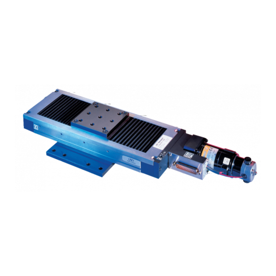
- Page 1 (M-) Mid-Range Travel Steel Linear Stages ’ ANUAL www.newport.com...
-
Page 2: Warranty
This warranty is in lieu of all other warranties, expressed or implied, including any implied warranty of merchantability or fitness for a particular use. Newport Corporation shall not be liable for any indirect, special, or consequential damages. No part of this manual may be reproduced or copied without the prior writ- ten approval of Newport Corporation. -
Page 3: Table Of Contents
5.2 Command Signals for Stepper Motors............8 5.3 DC-Motor Characteristics.................8 5.4 Command Signals for DC-Motors ............8 5.5 Sensor Position..................9 5.6 Feedback Signal Position................9 5.7 Pinouts......................10 — Connection to Newport Controllers ......11 6.1 Warnings on controllers.................11 6.2 Connection ....................12 6.3 Cables .......................12 — Connection to Non-Newport Controllers ....14... - Page 4 Safety: EIC 1010-1, safety standards for measurement, lab and control equipment. Newport Corporation shall not be liable for damages when using the product: • Modification of the product. • Using modified connector, or modified or not supplied cables. • Connecting this product to non-CE equipment.
-
Page 5: Warnings
Stop using the stage immediately, switch off the motor power and then disconnect the electronics power supply. After checking that smoke is no longer being emitted contact your Newport service facility and request repairs. Never attempt to repair the stage yourself as this can be dangerous. WARNING Make sure that this stage is not exposed to moisture and that liquid does not get into the stage. -
Page 6: Cautions
When the carriage is in end-of-run position, it is strongly recommended not to go beyond this point by using the manual knob as this may dam- age the stage mechanism. CAUTION Contact your Newport service facility to request cleaning and specifica- tion control every year. EDH0156En1030 – 01/03... -
Page 7: Introduction
(M-)UTM Mid-Range Travel Steel Linear Stages Mid-Range Travel Steel Linear Stages (M-)UTM Introduction This manual provides operating instructions for the stage that you have purchased in the (M-)UTM Series: • (M-)UTMPP1HL • (M-)UTMPE1V6 • (M-)UTMCC.1 • (M-)UTMMS1 • (M-)UTMPP.1 • (M-)UTMPE.1V6 •... -
Page 8: Description
Position measuring is performed with a 2000 pts/rev. encoder, integral with the motor shaft and a 2 mm pitch backlash compensated leadscrew. All (M-)UTM Series stages are equipped with a knurled knob for a manual con- trol. The modular design of (M-)UTM stages brings you the flexibility to choose the drive configuration that best matches your specific application require- ments: high-resolution 0.1 µm version or higher speed 1 µm version, manu-... -
Page 9: Design Details
Linear errors include: cosine errors, inaccuracy of screw or linear scale pitch, angular deviation at the measuring point (Abbe error) and thermal expansion effect. All Newport motion electronics can compensate for linear accuracy errors by step encoder correction. The relation between absolute accuracy and on-axis accuracy is as follow:... -
Page 10: Mechanical Specifications
(M-)UTM Mid-Range Travel Steel Linear Stages Resolution The smallest motion an encoder fixed to the stage can measure. Yaw, Pitch Rotation of carriage around the Z axis (Yaw) or Y axis (Pitch), when it moves. The testing of on-axis accuracy, repeatability, and reversal error are made sys- tematically with our test equipment in an air-conditioned room (20 °C ±1 °C Each stage is tested with a laser interferometer. -
Page 11: Load Characteristics And Stiffness
(M-)UTM Mid-Range Travel Steel Linear Stages Load Characteristics and Stiffness kαx (µrad/N.m) kαy (µrad/N.m) k α k α y Off-center load, Q ≤ Cz / (1 + D/50) + C x Cantilever distance in mm Normal center load capacity on bearings —... -
Page 12: Drive
(M-)UTM Mid-Range Travel Steel Linear Stages Drive Stepper Drive Versions Stepper-motor-driven stages are offered in four variants: • Two mini-step drive versions with resolutions of 1 µm (PP1HL) and 0.1 µm (PP.1). These combine high speed positioning and smooth displace- ment from 1/10-stepper encoder count driving mode. -
Page 13: Dc-Servo Drive Versions
(M-)UTM Mid-Range Travel Steel Linear Stages DC-Servo Drive Versions Four DC-motor-driven configurations are available: • Two high-power DC-Servo versions with resolutions of 1 µm (CC1HL) and 0.1 µm (CC.1). The CC1HL features a built-in tachometer to provide superior speed stability. •... -
Page 14: Motor
(M-)UTM Mid-Range Travel Steel Linear Stages Motor Stepper Motor Characteristics Angle by Step Current Resistance Inductance Newport Motor (°) (Ω) (mH) Utilization UE31PP 0.56 Full-Step UE41PP Full-Step or Mini-Step Command Signals for Stepper Motors Command Signals Command Signals UE31PP UE41PP... -
Page 15: Sensor Position
(M-)UTM Mid-Range Travel Steel Linear Stages ➊ When the stage moves in + Direction, the + Motor voltage is higher than – Motor voltage, and + Tacho Generator voltage is higher than – Tacho Generator voltage. ➋ When the stage moves in – Direction, the + Motor voltage is lower than –... -
Page 16: Pinouts
(M-)UTM Mid-Range Travel Steel Linear Stages Newport User Stage Encoder Phase A Pin #19 Encoder Phase A Pin #23 Encoder Phase B Pin #20 Output Signals Encoder Phase B Pin #24 Index Pulse Phase I Pin #15 Index Pulse Phase I... -
Page 17: Connection To Newport Controllers
(M-)UTM Mid-Range Travel Steel Linear Stages Connection to Newport Controllers Warnings on controllers Controllers are intended for use by qualified personnel who recognize shock hazards and are familiar with safety precautions required to avoid possible injury. Read the controller user’s manual carefully before operat- ing the instrument and pay attention to all written warnings and cautions. -
Page 18: Connection
(M-)UTM Mid-Range Travel Steel Linear Stages Connection On each stage is represented a label which indicates its name, its serial number and the motor it is equipped with (ex.: UE31PP). M-UTM100PE.1 ENCODER:5V MOTOR:UE31PP Stepper Motor U=30VDC I=1A WARNING Always turn the controller's power OFF before connecting to a stage. Stages may be connected to the rear panel motor connectors labeled “Motor…”... - Page 19 Mid-Range Travel Steel Linear Stages For applications where the standard 3-meter cable (MMCABLE-3) included with your stage is not adequate, Newport offers longer length cables designed to ensure the integrity of your positioning application. These cables are specially shielded and terminated with Newport’s stan- dard 25-pin sub-D connectors.
-
Page 20: Connection To Non-Newport Controllers
“Encoder” and “Index Pulse” are “differential pair” type output signals. Using these signals permits a high immunity to noise. Emission circuits generally used by Newport are 26LS31 or MC3487. Reception circuits to use are 26LS32 or MC3486. EDH0156En1030 – 01/03... -
Page 21: Mounting
(M-)UTM Mid-Range Travel Steel Linear Stages Mounting Stage Mountings WARNING Before to use a (M-)UTM stage, it is imperative to fix it: • directly on a rectified working surface, from holes located on the mounting plate, • on another stage, directly or with a mounting interface. but in no case, the stage has to remain without fastening. - Page 22 (M-)UTM Mid-Range Travel Steel Linear Stages ➋ Turn the stage upside down. ➌ Disassemble the base plate fixed on the body of the stage with 4 CHc .39 in. (10 mm) screws / 2.48 in. (63 mm). EDH0156En1030 – 01/03...
-
Page 23: Mounting On Working Surface
(M-)UTM Mid-Range Travel Steel Linear Stages Mounting on Working Surface ➊ Rotate the manual knob to move the carriage to provide access to the 2 holes on the bottom of the stage. ➋ Fasten the stage on the working surface with 2 M-CAP-M41 captive screws. -
Page 24: Assembling By The Carriage
Make steps of “Interfaces Disassembling” chapter in the opposite order. Assembly Pattern Stacking (M-)UTM Series stages either together or with other Newport stage is easily accomplished. Below are example schematics of the assembly pat- terns used. These interfaces are accessed by unscrewing and removing the upper and/or lower plates of the stages (see dimension drawing). -
Page 25: Dimensions
1.91 (48.5) CC1DD 4.6 (116.5) 1.26 (32) CC.1DD 6.2 (157.5) 1.26 (32) (M-)UTM Series XY assemblies are an economical choice when precision motion for light loads is required. These stages can be aligned to within 50 µrad orthogonality. EDH0156En1030 – 01/03... -
Page 26: Accessories: Eq100 Brackets
(M-)UTM Mid-Range Travel Steel Linear Stages 10.0 Accessories: EQ100 Brackets EQ100 Series right-angle brackets (to order separately) can be used for ver- tical mounting configurations of a (M-)UTM stage. 4 HOLES, M4 CLR ø 50 Dimension [in. (mm)] Model EQ100-S 5.3 (135) 5.1 (130.5) 4.1 (105) -
Page 27: Maintenance
CAUTION All disassembly attempts or repair of stage without authorization will void your warranty. 11.3 Calibration CAUTION It is recommended to return your stage to Newport once a year for a recalibration to its original specifications. EDH0156En1030 – 01/03... -
Page 28: Service Form
Service Form Your Local Representative Tel.: Fax: Name: Return authorization #: (Please obtain prior to return of item) Company: Address: Date: Country: Phone Number: P.O. Number: Fax Number: Item(s) Being Returned: Model #: Serial #: Description: Reasons of return of goods (please list any specific problems): EDH0156En1030 –... - Page 29 ( M - ) U T M Mid-Range Travel Steel Linear Stages CE Declaration of Conformity We declare that the accompanying product, identified with the “ ” mark, meets all relevant requirements of Directive: • 73/23/CEE, for Low Voltage Compatibility. •...
Need help?
Do you have a question about the UTM Series and is the answer not in the manual?
Questions and answers