Subscribe to Our Youtube Channel
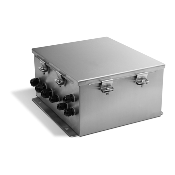
Summary of Contents for Rice Lake I/O Module
- Page 1 I/O Module For Intrinsically Safe Systems Version 2 Installation Manual PN 78076 Rev A...
-
Page 3: Table Of Contents
2.3 Installation of the I/O Module ........ - Page 4 Rice Lake continually offers web-based video training on a growing selection of product-related topics at no cost. Visit www.ricelake.com/webinars I/O Module - Intrinsically Safe...
-
Page 5: Introduction
Introduction This manual is intended for use by service technicians responsible for installing and servicing the I/O module. This manual applies to s using version 2.0 or newer software. I/O Module I/O Module Some procedures described in this manual require work inside the enclosure. -
Page 6: Installation
• It is mandatory to return the 320IS Plus to Rice Lake Weighing Systems for circuit board level service. Component level repair is not permitted on UL-approved equipment by anyone other than the manufacturer. Unpacking and Assembly Immediately after unpacking, visually inspect the to ensure all components are included and undamaged. - Page 7 TD(B) TVS6 AGND TVS1 TVS3 Figure 2-1. I/O Module Board Figure 2-2. CN8 - DC Power Connector must be installed in a safe area. The internal power supply unit provides DC voltage for the 320IS Plus 320IS ’s main board. The DC power requirements of the I/O panel are as follows: Plus •...
-
Page 8: Ac Wiring/Installation
3. Screw the connector locking nut down to a snug fit, locking the fiber in place. 4. Secure duplex fiber optic cable to wire tie mounting button located on I/O Module circuit board (see Figure 2-1 on page 3) using wire ties included in parts kit. -
Page 9: Rs-485 Communications
5 below for information on connecting RS-422 communications. Description (Sign) Signal Ground (GND) 2 - 4 — RS-422 input (R+) RS-422 input (R-) RS-422 output (T+) RS-422 output (T-) Table 2-5. RS-422 Connections (CN2 and CN3) I/O Module Figure 2-4. Typical RS-422 Wiring Paths Installation... -
Page 10: 20Ma Current Loop
Table 2-9 below. See Figure 2-1 on page 3 for the location of CN1 and DIP switches. Name Ground (Analog Output 1 Common) Analog Output 1 (current) Analog Output 1 (voltage) Analog Output 2 (current) Analog Output 2 (voltage) Ground (Analog Output 2 Common) Table 2-9. CN1 Connectors I/O Module - Intrinsically Safe... -
Page 11: Digital Inputs
Digital Inputs has four digital inputs that can be used to control pre-defined operations in the indicator. Table 2-10 320IS Plus outlines the various functions for the digital inputs. Digital inputs are available on connector CN4 (see Figure 2-1 on page 3). All inputs are individually isolated via opto-couplers. -
Page 12: Board Removal
VDC. Life expectancy of the battery is seven years. See Figure 2-1 on page 3 for battery board battery location and orientation (positive side up). Risk of explosion if battery is replaced with incorrect type. Dispose of batteries per manufacturer instruction. I/O Module - Intrinsically Safe... - Page 13 1.75 7.50 4x Ø.25 10.84 (11.63) Tighten until clamps bottom out to fully compress gasket (12.90) Figure 2-5. 320IS Plus Enclosure Dimensions Installation...
- Page 14 Figure 2-6. 320IS Plus Assembly I/O Module - Intrinsically Safe...
-
Page 15: Configuration
Baud Rate, Parity, Stop Bits, End of Line Delay, Termination, Port Interface, Address for RS-485 Operation Analog Output Output (voltage, current), Error Action (full scale, hold, zero scale), Tweak Zero Value, Tweak Span Value Digital Output Output (On/Off) Enable Mask Digital Input Enable Mask Table 3-1. Configuration Parameters Sent to I/O Module Configuration... -
Page 16: Appendix
Contact Resistance 30m Operate (Set) Time 10ms Max Release (Reset) Time 10ms Max LED Annunciators SMD LEDs indicate closed state Digital Inputs Incoming Signal Range 0-24V (TTL level) Interfacing Circuitry Opto-couplers with 5KV isolation voltage rating I/O Module - Intrinsically Safe... - Page 17 Limited Warranty Rice Lake Weighing Systems (RLWS) warrants that all RLWS equipment and systems properly installed by a Distributor or Original Equipment Manufacturer (OEM) will operate per written specifications as confirmed by the Distributor/OEM and accepted by RLWS. All systems and components are warranted against defects in materials and workmanship for two years.
- Page 18 I/O Module - Intrinsically Safe...
- Page 20 Specifications subject to change without notice. Rice Lake Weighing Systems is an ISO 9001 registered company. 230 W. Coleman St. • Rice Lake, WI 54868 • USA U.S. 800-472-6703 • Canada/Mexico 800-321-6703 • International 715-234-9171 • Europe +31 (0)26 472 1319 www.ricelake.com www.ricelake.mx www.ricelake.eu www.ricelake.co.in...


Need help?
Do you have a question about the I/O Module and is the answer not in the manual?
Questions and answers