Table of Contents
Advertisement
Quick Links
Advertisement
Table of Contents

Subscribe to Our Youtube Channel
Summary of Contents for Pittsburgh Modular Lifeforms Touch Controller
- Page 1 The Voltage Research Laboratory Encyclopedia Touch Controller Manual...
-
Page 2: Thank You
The Touch Controller is a large part of the unique vision for analog synthesis that Michael and I share. Enjoy, Richard Nicol Founder | Product Design Pittsburgh Modular Synthesizers Voltage Research Laboratory Team Product Design: Richard Nicol Analog Engineering: Michael Johnsen Logistics: Michael Importico... -
Page 3: Important Information
-12v. This stripe needs to line up with the -12v pins on the power rail and the -12v pins on the module. The Lifeforms Touch Controller includes reverse polarity protection so it will not be damaged when plugged in incorrectly; however, as a general rule, failure to match up the pins correctly can result in damage to one or all the modules in a case. -
Page 4: Table Of Contents
Table of Contents Thank you! Important Information Table of Contents User Interface Controls Module Overview User Interface Conventions Left and Right Touch Zones Controller Modes Mono Mode Sequences Duo Mode Sequences Scan Mode Eurorack Specs Warranty Service and Other Information... -
Page 5: User Interface Controls
User Interface Controls 1. Channel Animator Section 34. Channel 5 Voltage Preset Knob A 2. Left Output Section 35. Channel 6 Voltage Preset Knob A 3. Right Output Section 36. Channel 7 Voltage Preset Knob A 4. All Output Section 37. -
Page 6: Module Overview
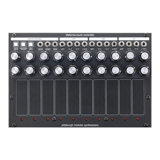
Module Overview The Touch Controller is an interface for interacting with gates and voltages. The module features 10 Touch Plates, each with 2 assignable analog voltage presets, Y-Axis response, gate response, multiple performance modes, and pattern sequencing. The interface of the Touch Controller was designed to be intuitive with direct access to all of the functions. -
Page 7: User Interface Conventions
User Interface Information There are some user interface and general patching conventions that need to be understood to achieve the best results from the Touch Controller. Touch Plates The Touch Controller has 10 Touch Plates. The Touch Plate checks for on/off status and reads the finger position along the Y-Axis. - Page 8 User Interface Information Section (2 of 2) Patch Points The Touch Controller uses Eurorack standard 1/8” mono jacks for all the patch points. Input jacks have an outline around their name. Output jacks do not. The Touch Controller interface does not distinguish between audio, CV, and gate signals.
-
Page 9: Left And Right Touch Zones
Left & Right Touch Zones 10 11 12 13 14 15 16 17 18 19 20 21 22 Left & Right Touch Zones The Touch Controller is split into 2 Touch Zones, Left and Right, each with 5 Touch Plates. The Touch Zones allow the Touch Controller to always function as a pair of standalone touch interfaces. -
Page 10: Controller Modes
Controller Modes Mono and Duo Controller Modes The Touch Controller operates in 2 different modes. Mono and Duo. Select the active mode by pressing the MONO BUTTON (5) or DUO BUTTON (7) in the CHANNEL ANIMATOR SECTION (1). Mono Mode In Mono mode, the Touch Controllers operates like a single, monophonic 10 Touch Plate controller. -
Page 11: Mono Mode Sequences
Mono Mode Sequencing Mono Mode Sequencing The Touch Controller can quickly create sequences using the Channel Animator section. A Mono sequence utilizes the Left, Right, and All Output Jacks. The ALL OUTPUT SECTION is updated with every active step. If the active step is in the Left Zone, the LEFT OUTPUT SECTION is updated, if the active step is in the Right Zone, the RIGHT OUTPUT SECTION is updated. - Page 12 Mono Mode Sequencing Section (2 of 2) Programming a Sequence In Mono Mode, the Sequencer treats all 10 Touch Plates as a single monophonic touch interface. A sequence is recorded by pressing and holding the MONO BUTTON (5). While the MONO BUTTON (5) remains pressed, up to 64 steps can be added to the sequence by tapping the Touch Plates.
-
Page 13: Duo Mode Sequences
Duo Mode Sequencing Duo Mode Sequencing The Touch Controller can quickly create 1 or 2 simultaneous sequences using the Channel Animator section. The Left and Right Zones can be used to create 2 independent sequences. If the Left Zone sequence is active, the LEFT OUTPUT SECTION is updated, if the Right Zone sequence is active, the RIGHT OUTPUT SECTION is updated. - Page 14 Duo Mode Sequencing Section (2 of 2) Resetting Both Sequences The sequences can be reset to step 1 a few different ways. Pressing the RESET/REST BUTTON (6) resets both sequences to step 1. Sending a trigger or gate signal into the RESET INPUT JACK (9) also resets both sequences to step 1.
-
Page 15: Scan Mode
Scan Mode The r Scan Mode Active Channel Sequencing The SCAN INPUT JACK (8) of the Touch Controller accepts a 0v to 5v control voltage signal and sets the active channel based on the incoming voltage. The Scan Input updates the active channel when the incoming voltage changes. -
Page 16: Eurorack Specs
Please use a clean, high quality power source for optimum performance. Warranty For a period of one year after the date of original purchase, the Lifeforms Touch Controller manufactured by Pittsburgh Modular Synthesizers LLC, is warranted to function properly and be free of defects in materials and workmanship. - Page 17 Pittsburgh Modular Synthesizers...
Need help?
Do you have a question about the Lifeforms Touch Controller and is the answer not in the manual?
Questions and answers