Advertisement
Quick Links
Deaf & Hearing Impaired
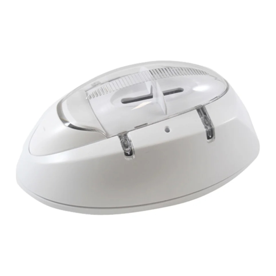
RadioLINK Alarm System
Strobe Light & Vibration Pad Module
For use with RF Smoke/Heat/CO Alarms
Model Ei170RF
Model Ei171RF
Note: At least one RF Smoke/CO/Heat Alarm is required to make the Ei170RF / Ei171RF
Alarm operational. This is not supplied with the Ei170RF / Ei171RF and must be obtained
Important: Read these instructions, together with those from the separate RF Smoke/CO/
Heat Alarms and accessories before installation. All instruction leaflets must be left with the
RadioLINK Alarm System with Strobe & Vibration Pad
RadioLINK Alarm System with Strobe
separately.
end user after installation.
Models: Ei170RF
Ei171RF
(Smoke / Heat / CO Alarm
supplied separately)
(Only)
1
Advertisement

Subscribe to Our Youtube Channel
Related Manuals for Ei Electronics Ei170RF


Summary of Contents for Ei Electronics Ei170RF
- Page 1 Model Ei171RF RadioLINK Alarm System with Strobe (Only) Note: At least one RF Smoke/CO/Heat Alarm is required to make the Ei170RF / Ei171RF Alarm operational. This is not supplied with the Ei170RF / Ei171RF and must be obtained separately. Important: Read these instructions, together with those from the separate RF Smoke/CO/ Heat Alarms and accessories before installation.
- Page 2 1. Introduction This leaflet describes the installation of the Ei170RF / Ei171RF and its integration into a total RF Fire Alarm System, incorporating a choice of RF Smoke/CO/Heat Alarms and Accessories. Note: It is essential that the Ei170RF / Ei171RF is connected to the mains to preserve its one-week battery standby.
- Page 3 Battery Battery Plug Latch Figure 2 Battery Clearance Notch Figure 3 Shows battery orientation - Dress the battery leads as shown, replace the battery cover and push firmly down on the two latches If fixing to a wall, the screws should be spaced 95mm (3.7 inches) horizontally apart. The top screws will be 70mm (2.7 inches) below the top surface of the Strobe Module when installed.
- Page 4 A system with 3 Smoke Alarms and 1 Ei170RF / Ei171RF will result in 4 flashes. It may take up to 10 minutes before all 4 flashes are seen. The flash pattern will repeat every 5 to 10 seconds while the Ei170RF / Ei171RF remains in house code mode.
- Page 5 Mains RadioLINK Indicator Indicator Green Blue (mains disconnected = amber flash/ 4 seconds) House Code Button Strobe Alarm Fault Indicator Indicator Amber ALARM FAULT TEST Test Button Figure 4...
- Page 6 3. After prolonged absence from the dwelling (e.g. after holiday period). 4. After repair or servicing of any of the systems elements or electrical works being carried out. 4.1 With regards to the Ei170RF / Ei171RF: 4.1.1 Check that the mains indicator on the strobe is on continuously (green light).
-
Page 7: Troubleshooting
At this point release the House Code button. The Ei170RF / Ei171RF is now reset. To reset the other devices in the system, consult the appropriate instruction manuals. Once all devices are reset, repeat the House Coding procedure (see the Setting up the RadioLINK System section). - Page 8 9. Guarantee Ei Electronics guarantees this device for five years from the date of purchase against any defects that are due to faulty materials or workmanship. If this device should become defective within the guarantee period, we shall at our discretion repair or replace the faulty unit.
- Page 9 Vibration Pad Remove (Ei170RF) protection Conversion Jack plug before (Ei171RF) connecting accessories 180mA(max) 20mA(max) Aux1 Aux2 Template for Mounting Screws Drill Holes Here Figure 5...
-
Page 11: Indicator Summary
Indicator Summary Control Panel Indicators RadioLINK Mains Indicator Indicator Blue Green (mains disconnected = amber flash/ 4 seconds) Strobe Fault Alarm Indicator Indicator ALARM Amber FAULT TEST... - Page 12 0889 Hereby, Ei Electronics declares that this Ei170RF / Ei171RF RadioLINK Alarm System is in compliance with the essential requirements and other relevant provisions of Directive 2014/53/EU. The Declaration of Conformity may be consulted at www.eielectronics.com/compliance Aico Ltd.
Need help?
Do you have a question about the Ei170RF and is the answer not in the manual?
Questions and answers