
Subscribe to Our Youtube Channel
Related Manuals for Knick SensoGate WA 133 Series


Summary of Contents for Knick SensoGate WA 133 Series
- Page 1 The Art of Measuring. SensoGate WA 133 User Manual Retractable Fitting with PTFE Process Adaptation Latest Product Information: www.knick.de...
-
Page 2: Table Of Contents
Table of Contents SensoGate WA 133 Safety Information ........................... 3 Symbols and Markings ..................................5 List of Currently Known Hazardous Substances ........................6 Intended Use ............................. 7 Rating Plates .....................................8 Package Contents ...................................8 SensoGate WA 133 Product Code ....................9 Function Description ........................10 Control Air and Feedback ................................ -
Page 3: Safety Information
‘SensoLock‘ safety function. NOTICE: Process-Related Risks! Knick Elektronische Messgeräte GmbH & Co. KG assumes no liability for damages caused by process-related risks known to the operator, which would in fact not permit the use of the retractable fitting. - Page 4 Exceeding the standard atmospheric conditions within the manufacturer’s specifications, such as ambient tem- perature, process pressure and temperature, does not impair the durability of the retractable fittings. Related certificates are included in the product’s scope of delivery and are available at www.knick.de in the cur- rent version.
-
Page 5: Symbols And Markings
Insertion fitting Insertion fitting Type Made in Germany Made in Germany be / Drive unit robe / Drive unit Type Type 4 to 7 bar 4 to 7 bar 7 bar Safety Information max. 7 bar max. 7 bar . 7 bar 0 °C Made in Germany Made in Germany... -
Page 6: List Of Currently Known Hazardous Substances
Safety Information SensoGate WA 133 List of Currently Known Hazardous Substances List of currently known hazardous substances according to EN 626-1 that have been used with this type of retractable fitting: Hazardous substance Hazard Remark Argon Asphyxiating Asbestos Fibrogenic Benzene Carcinogenic Hydrogen cyanide Blood poisoning... -
Page 7: Intended Use
NOTICE: Safe Use of the Retractable Fitting! If you are not sure whether the retractable fitting can be safely used for your intended application, contact Knick! To ensure safe use of the equipment, you must observe the temperature and pressure ranges given in the Specifications of this user manual. -
Page 8: Rating Plates
Intended Use SensoGate WA 133 Trademarks The following trademarks are used in this manual without further marking: SensoGate®, Unical®, Uniclean®, Protos® are registered trademarks of Knick Elektronische Messgeräte GmbH & Co. KG, Germany Rating Plates SensoGate® WA 133-N Drive ®... -
Page 9: Sensogate Wa 133 Product Code
SensoGate WA 133 Product Code SensoGate WA 133 WA 133- Explosion For ATEX Zone 0 protection Without Sensor Sensor, Ø 12 mm, with PG 13.5 pH sensor, Ø 12 mm, pressurized Gasket material EPDM EPDM - FDA FKM - FDA FFKM - FDA FFKM Process-wetted... -
Page 10: Function Description
Function Description SensoGate WA 133 The pneumatically operated retractable fitting can be moved to two positions: • PROCESS position: The sensor is located in the process medium. • SERVICE position: The sensor is located in the calibration chamber. To replace the sensor, you must move the retractable fitting to the SERVICE position (see “SERVICE Position”... -
Page 11: Overview Of Retractable Fitting
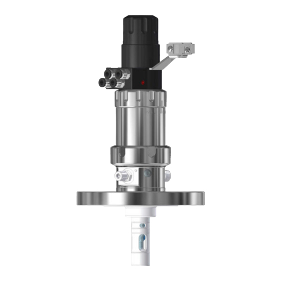
Overview of Retractable Fitting SensoGate WA 133 The SensoGate retractable fitting has a modular design. This allows the drive unit, immersion tube and process adaptation to be exchanged. The retractable fitting consists of two main units: • The drive unit performs the movements required to move the sensor into and out of the process. -
Page 12: Modular Design: Drive Unit, Immersion Tube, Process Adaptation
Overview of Retractable Fitting SensoGate WA 133 Modular Design: Drive Unit, Immersion Tube, Process Adaptation Drive Units Short immersion depth Long immersion depth Short immersion depth Sensors with Sensors with Sensors with solid electrolyte solid electrolyte liquid electrolyte Immersion Tubes Immersion tube Material: PTFE Bayonet coupling... - Page 13 SensoLock – Safety Function SensoGate WA 133 Optionally, the retractable fitting is equipped with the ‘SensoLock‘ safety function. The safety func- tion consists of a rotatable ring that mechanically blocks the travel movement of the retractable fitting. The ring can only be rotated when in SERVICE position. In PROCESS position and all inter- mediate positions the ring is secured.
-
Page 14: Assembly
Assembly SensoGate WA 133 Mounting the Retractable Fitting • Possible mounting angle 15° above horizontal • Mounting angle 360° (i.e. even upside down) for special sensors only containing thickened 15° 15° electrolytes which thus cannot flow. Installing the Outlet and Inlet Hoses NOTICE: Always install both hoses to ensure safe operation! To ensure safe operation of the retractable fitting, you must connect the inlet and outlet hoses and make sure that the cleaning and calibration solutions are collected! -
Page 15: Service Position
SERVICE Position SensoGate WA 133 The following illustrations clearly show the SERVICE position: Short immersion depth Short immersion depth Long immersion depth Solid-electrolyte sensor Liquid-electrolyte sensor Solid-electrolyte sensor The SERVICE position is The SERVICE position is indi- The SERVICE position is indi- indicated by the sensor cated by the rubber bellows cated by the service cap (L) -
Page 16: Process Position
PROCESS Position SensoGate WA 133 The following illustrations clearly show the PROCESS position: Short immersion depth Short immersion depth Long immersion depth Solid-electrolyte sensor Liquid-electrolyte sensor Solid-electrolyte sensor The PROCESS position is The PROCESS position is The PROCESS position is indi- indicated by the sensor indicated by the rubber bel- cated by the service cap not... -
Page 17: Installing And Removing A Sensor
Installing and Removing a Sensor SensoGate WA 133 NOTICE: Sensor Installation or Removal by Qualified Personnel Only! Sensors shall only be installed or removed by personnel authorized by the operating company and trained in the handling of the retractable fitting. Preparations: •... -
Page 18: Sensors With Solid Electrolyte
3. Insert the sensor and screw in the sensor head (J) (19 mm A/F, PG 13.5 thread) with a max. torque of 3 Nm (recommended tool: 19 mm mounting wrench, e.g., Knick ZU 0647). Note: When tightening the sensor, you must overcome the elastic force of the internal sensor monitoring. -
Page 19: Removing The Sensor
(process seal- ing might be defective). 4. Remove the sensor (recommended tool: 19 mm mounting wrench, e.g., Knick ZU 0647). 5. Check whether the slide washer (C) or the O-ring (D) are damaged. NOTICE: Glass Breakage! -
Page 20: Long Immersion Depth
3. Insert the sensor and screw in the sensor head (J) (19 mm A/F, PG 13.5 thread) with a max. torque of 3 Nm (recommended tool: 19 mm mounting wrench, e.g., Knick ZU 0647). Note: When tightening the sensor, you must overcome the elastic force of the internal sensor monitoring. -
Page 21: Removing The Sensor
6. Disconnect the cable jack (G) from the sensor. 7. Screw off the sensor head (J) (19 mm, PG 13.5) and pull out the sensor (recommended tool: 19 mm mounting wrench, e.g., Knick ZU 0647). NOTICE: Glass Breakage! When replacing damaged sensors (glass... -
Page 22: Sensors With Liquid Electrolyte
Installing the Sensor Conditions: • Sensor: 250 mm, Ø 12 mm, e.g., Knick SE 551 • Air pressure in the sensor pressure chamber: 0.5 to 1 bar above that of the process medium to ensure that the electrolyte flows from the reference electrode to the process medium Note: Observe the user manual of the sensor. -
Page 23: Removing The Sensor
Sensors with Liquid Electrolyte SensoGate WA 133 Removing the Sensor Before removing the sensor, make sure that the retractable fitting is in SERVICE position (see page 17 for information on installing or removing a sensor). 1. Remove the cable jack. 2. -
Page 24: Drive Unit
Drive Unit SensoGate WA 133 Removing the Drive Unit NOTICE: No Process Pressure! Make sure that the fitting is disconnected from process pressure! Take appropriate safety precautions against escaping process fluids. Note: Follow the steps below in the correct order. 1. -
Page 25: Installing The Drive Unit
Drive Unit SensoGate WA 133 Installing the Drive Unit Note: Follow the steps below in the correct order. 1. Insert the drive unit into the process adaptation (P) (in SERVICE position). The radial position of the drive unit is determined by a coding pin (O) in the calibration chamber and an opening (AJ) in the drive unit. -
Page 26: Immersion Tube
Immersion Tube SensoGate WA 133 The wetted part of the immersion tube is made of PTFE. The upper part of the immersion tube (T) is provided with a stainless steel endpiece with bayonet contour (U). This endpiece serves for con- necting the immersion tube to the drive unit of the retractable fitting. -
Page 27: Removing The Immersion Tube
Immersion Tube SensoGate WA 133 Removing the Immersion Tube Conditions: First, separate the immersion tube from the process adaptation (see “Removing the Drive Unit” chapter). 1. Move the drive unit to PROCESS position until the two screws (Z) become visible. Loosen the two screws (Z) using a screwdriver (TX 25) until they contact the stop at the immersion tube (see illustration). -
Page 28: Installing The Immersion Tube
Immersion Tube SensoGate WA 133 Installing the Immersion Tube Conditions: The retractable fitting must be in PROCESS position (see “PROCESS Position” chapter). 1. Push the O-ring (D) (sensor gasket) onto the sensor (A) as shown. 2. Note: Make sure that there is no further O-ring in the immersion tube (T) (installed by mistake). -
Page 29: Calibration Chamber
Calibration Chamber SensoGate WA 133 Removing the Calibration Chamber 1. Screw off the outlet (AM) and inlet connectors (AV). Take off the loose flange if required. 2. Loosen and remove the two screws (AK) from the calibration chamber (using screwdriver TX25). -
Page 30: Installing The Calibration Chamber
Calibration Chamber SensoGate WA 133 Installing the Calibration Chamber 1. Align the guiding edges (AI) of the calibration chamber (K) and insert it in the process adaptation (P). 2. Always secure the calibration chamber with both screws (AK). 3. Install the loose flange (LF) if required. -
Page 31: Installation Dimensions
Installation Dimensions SensoGate WA 133 WA 133, Short Immersion Depth for Sensors With Solid Electrolyte... - Page 32 Installation Dimensions SensoGate WA 133 WA 133 for Sensors with Liquid Electrolyte...
- Page 33 Installation Dimensions SensoGate WA 133 WA 133, Long Immersion Depth for Sensors With Solid Electrolyte...
- Page 34 Installation Dimensions SensoGate WA 133 Process Adaptation Loose flange, DIN DN32 ... DN100 ANSI 316, 1½" ... 3" short and long immersion depth...
-
Page 35: Specifications
Specifications SensoGate WA 133 Permissible process pressure 6 bar (at 0 ... 40 °C) and temperature 6 bar (40 °C), falling linearly to 3 bar (100 °C) 3 bar (max. 1 hour) at 135 °C Permissible pressure for probe control 4 ... -
Page 36: Maintenance
Maintenance SensoGate WA 133 NOTICE: Shut Off Process Medium, Process Pressure, and Compressed Air! Before starting maintenance work, you must separate the retractable fitting safely from the process: Make sure that it is disconnected from all process media and process pressure. Maintenance Intervals Due to the differing process conditions (pressure, temperature, chemically aggressive media etc.), we can only give recommendations for maintenance intervals. -
Page 37: Servicing The Drive Unit
Maintenance SensoGate WA 133 Servicing the Drive Unit The drive unit must be removed, for example: • for general maintenance or inspection • to clean the calibration chamber, e.g., after a sensor has broken • to change the sensor / calibration-chamber gaskets •... -
Page 38: Sealing Kits For Maintenance And Servicing
Maintenance SensoGate WA 133 Sealing Kits for Maintenance and Servicing Note: The sealing kits come with detailed illustrations for installation. The new O-rings must be lubricated with the included lubricant. The sealing kits are available in different materials. The smaller sealing kits (“Set X/1”) only contain gaskets for direct contact with the process. The extended sealing kits (“Set X/2”) also include gaskets for contact with the rinse medium. -
Page 39: Accessories / Spare Parts
Accessories / Spare Parts SensoGate WA 133 Note: Use only accessories and spare parts from Knick or a company authorized by Knick. For ordering, use the part numbers beginning with F-ZU, e.g., F-ZU 0680. F-ZU 0680 SensoGate Service Set, Basic These tools are suitable for minor maintenance operations. -
Page 40: Declaration Of Contamination
I have answered the above questions to the best of my knowledge. Name: Company: Date: Signature: Knick Elektronische Messgeräte GmbH & Co. KG, Beuckestraße 22, 14163 Berlin, Germany Phone +49 (0) 30 801 91 - 0 / Fax +49 (0) 30 801 91-200 E-mail: knick@knick.de / Internet: www.knick.de... -
Page 41: Index
Index SensoGate WA 133 Inspection intervals 35 Installation dimensions 30 Accessories 38 Electrostatic charging 3 Installing a sensor 16 Air supply, accessory 38 Equipotential bonding cable 21 Installing liquid-electrolyte Ambient temperature 4 EU Declaration of Conformity 39 sensors 21 Ambient temperature (Ex) 34 Extension, safety function 20 Installing solid-electrolyte Assembly, calibration chamber 29... - Page 42 Index SensoGate WA 133 Package contents 7 Safety function: Extension 20 Tamb 4 Plug-in adapter 38 Safety function: SensoLock 12 Technical data 34 Pressurized sensors 34 Safety information 3 Temperature ratings 34 Pressurized sensors, air supply 38 Screwdriver (TX 25) 26 Terminal, equipotential Process adaptation, Screws, immersion tube 26...
-
Page 43: Annotations
Annotations SensoGate WA 133... - Page 44 2020 Subject to change © Knick Elektronische Messgeräte GmbH & Co. KG Beuckestraße 22 14163 Berlin Germany Phone: +49 30 80191-0 Fax: +49 30 80191-200 Email: info@knick.de Internet: www.knick.de TA-215.501-KNEN02 20200623 097348...
Need help?
Do you have a question about the SensoGate WA 133 Series and is the answer not in the manual?
Questions and answers