Table of Contents
Advertisement
Quick Links
GETTING STARTED GUIDE
NI PXIe-5673E
6.6 GHz RF Vector Signal Generator
Note
Before you begin, install and configure your chassis and controller.
This document explains how to install, configure, and test the NI PXIe-5673E (NI 5673E).
The NI 5673E is a 6.6 GHz RF vector signal generator (VSG) with RF list mode. The
NI 5673E ships with the NI-RFSG instrument driver, which you use to program the device.
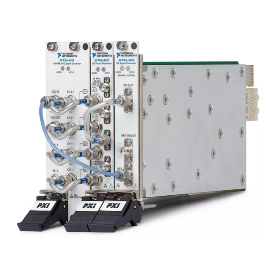
The NI 5673E comprises the following devices:
•
NI PXIe-5450/5451 (NI 5450/5451) arbitrary waveform generator (AWG) module
•
NI PXIe-5611 (NI 5611) I/Q modulator module
•
NI PXIe-5650/5651/5652 (NI 5650/5651/5652) local oscillator (LO) source module
To access NI 5673E documentation, navigate to Start»All Programs»National Instruments»
NI-RFSG»Documentation.
The specifications document for your device is installed with the driver software. Refer to
ni.com/manuals
for the most recent specifications for your device.
Caution
manner not described in this document.
Hot Surface
temperatures and cause burns. Allow the NI 5673E to cool before removing it from
the chassis.
Contents
Electromagnetic Compatibility Guidelines............................................................................... 2
Verifying the System Requirements..........................................................................................2
Unpacking the Kit..................................................................................................................... 2
Verifying the Kit Contents................................................................................................ 4
Preparing the Environment....................................................................................................... 5
Installing the Software.............................................................................................................. 5
Installing the NI 5673E............................................................................................................. 6
Interconnecting the NI 5673E Modules............................................................................ 8
Configuring the NI 5673E in MAX........................................................................................ 17
The protection provided by this product may be impaired if it is used in a
If the NI 5673E has been in use, it may exceed safe handling
Advertisement
Table of Contents

Related Manuals for NI PXIe-5673E


Summary of Contents for NI PXIe-5673E
-
Page 1: Table Of Contents
This document explains how to install, configure, and test the NI PXIe-5673E (NI 5673E). The NI 5673E is a 6.6 GHz RF vector signal generator (VSG) with RF list mode. The NI 5673E ships with the NI-RFSG instrument driver, which you use to program the device. -
Page 2: Electromagnetic Compatibility Guidelines
Troubleshooting........................24 Why Is the ACCESS LED Off When the Chassis is On?..........24 What Should I Do if the NI 5673E Doesn't Appear in MAX?........24 What Should I Do if the Module Fails the Self-Test?.............25 What Should I Do if the Thermal Shutdown Error Appears?.........25 Where to Go Next........................ - Page 3 Caution Never touch the exposed pins of connectors. Notify NI if the device appears damaged in any way. Do not install a damaged device. Unpack any other items and documentation from the kit. Store the device in the antistatic package when the device is not in use.
-
Page 4: Verifying The Kit Contents
12. Read Me First: Safety and Electromagnetic B, Part Number 198774-01 Compatibility 6. Semi-Flexible SMA-to-SMA Cable, Part Number 13. Maintain Forced-Air Cooling Note to Users 190412-05 7. SMA Driver Bit, Part Number 190487A-01 4 | ni.com | NI PXIe-5673E Getting Started Guide... -
Page 5: Preparing The Environment
• A 1 N · m standard SMA torque wrench (NI part number 780487-01). Preparing the Environment Ensure that the environment you are using the NI 5673E in meets the following specifications................Operating ambient temperature 0 °C to 55 °C (IEC 60068-2-1, IEC 60068-2-2) ................ -
Page 6: Installing The Ni 5673E
Note to Users included with the module to ensure that the chassis can cool the device effectively. To use the included cables, you must install the NI 5611 I/Q modulator module in the slot immediately to the right of the NI 5450/5451 AWG module, and you must install the NI 5650/5651/5652 LO source module in the slot immediately to the right of the NI 5611 I/Q modulator module. - Page 7 NI 5673E modules can be placed in PXI Express peripheral slots or PXI Express Hybrid peripheral slots. Touch any metal part of the chassis to discharge static electricity. Ensure that the ejector handle is in the unlatched (downward) position. Place the module edges into the module guides at the top and bottom of the chassis. Slide the device into the slot until it is fully inserted.
-
Page 8: Interconnecting The Ni 5673E Modules
4. 50 Ω Termination Load 2. Rigid SMA-to-SMA Cable, Labeled A Use the Cable A center pin to connect the CH 1-/Q- connector of the NI 5450/5451 front panel to the Q- connector of the NI 5611 front panel. Note... - Page 9 The amount of bending should be minimal. The cables can be damaged by excessive bending. Use the Cable A center pin to connect the CH 1+/Q+ connector of the NI 5450/5451 front panel to the Q+ connector of the NI 5611 front panel.
- Page 10 • If you are using an active device, such as a preamplifier or switch routed to the NI 5673E, ensure no signal transients are sourced to the NI 5673E. NI 5611 I/Q Modulator Module The NI PXIe-5611 I/Q modulator module contains eight connectors and two multicolor LEDs.
- Page 11 PLS MOD Input for the 3.3 V TTL for pulse-modulating the RF signal. LO IN Connects to the RF OUT connector on the NI 5650/5651/5652 front panel. This connector routes the local oscillator from the NI 5650/5651/5652 to the NI 5611.
- Page 12 The NI PXIe-5450/5451 AWG module contains eight connectors and two LEDs. Note The following figure depicts the NI 5450 module front panel, although both the NI 5450 and NI 5451 module front panels contain the same connectors and LEDs. 12 | ni.com | NI PXIe-5673E Getting Started Guide...
- Page 13 Figure 6. NI 5450 AWG Module Front Panel Table 4. Device Front Panel Icon Definition Refer to the user documentation for required maintenance measures to ensure user safety and/or preserve the specified EMC performance. NI PXIe-5673E Getting Started Guide | © National Instruments | 13...
- Page 14 Sample Clock timebase to the external Reference Clock. The signal input to this connector can also be used as a Sample Clock source. CLK OUT Connects to the REF IN/OUT connector on the NI 5650/5651/5652 front panel. This connector provides a clock signal that can be shared by other devices.
- Page 15 RED—The module has detected an error state; this state may indicate a PLL lock failure or a thermal shutdown condition. NI 5650/5651/5652 RF Signal Generator Module The NI 5650/5651/5652 RF signal generator module contains three connectors and two multicolor LEDs. Note The following figure depicts the NI 5652 module front panel, although each NI 5650/5651/5652 module front panel contains the same connectors and LEDs.
- Page 16 Figure 7. NI 5652 RF Signal Generator Module Front Panel RF Signal Generator ACCESS ACTIVE 500 kHz - 6.6 GHz RF OUT Ω 0.5 W Reverse Power REF IN/OUT Ω 5 Vp-p OUT: 1 Vp-p OUT2 Ω 1 Vp-p Table 7. Device Front Panel Icon Definitions Refer to the user documentation for required maintenance measures to ensure user safety and/or preserve the specified EMC performance.
-
Page 17: Configuring The Ni 5673E In Max
Use Measurement & Automation Explorer (MAX) to configure your National Instruments hardware. MAX informs other programs about which devices reside in the system and how they are configured. MAX is automatically installed with NI-RFSG. Launch MAX. NI PXIe-5673E Getting Started Guide | © National Instruments | 17... - Page 18 Self-test the device modules by selecting the modules in the configuration tree, and clicking Self-Test in the MAX toolbar. Repeat this step for all modules in your NI 5673E system. The MAX self-test performs a basic verification of hardware resources.
-
Page 19: Programming The Ni 5673E
Started section of the NI RF Signal Generators Help. Refer to the Creating an Application with Microsoft Visual C and C++ topic of the NI RF Signal Generators Help to manually add all required include and library files to your project. -
Page 20: Generating A Signal Using The Ni-Rfsg Soft Front Panel
You can use the Search button on the Functions palette to find the NI- RFSG palette. Add the core NI-RFSG VIs from the NI-RFSG palette to the block diagram, and wire the VIs together as shown in the following figure. - Page 21 (100 MHz). 100M 12. In the VI front panel resource name control, enter the NI 5611 I/Q modulator device name that you specified in MAX. Adding a While Loop Add a While Loop to continuously generate the signal and check the generation status until you click the Stop button.
- Page 22 Create an error indicator by right-clicking the error out output of the niRFSG Close VI and selecting Create»Indicator. Verify that the VI block diagram and VI front panel now look similar to the following figures. 22 | ni.com | NI PXIe-5673E Getting Started Guide...
- Page 23 Figure 12. Basic Sine Wave Generation VI Block Diagram Figure 13. Basic Sine Wave Generation VI Front Panel Open the VI front panel, and select the NI 5611 I/Q modulator module name specified in MAX in the resource name control.
-
Page 24: Troubleshooting
Troubleshooting If an issue persists after you complete a troubleshooting procedure, contact NI technical support or visit ni.com/support. Why Is the ACCESS LED Off When the Chassis is On? The LEDs may not illuminate until the device has been configured in MAX. Before proceeding, verify that the NI 5673E appears in MAX. -
Page 25: What Should I Do If The Module Fails The Self-Test
What Should I Do if the Thermal Shutdown Error Appears? The thermal shutdown error appears when device temperatures exceed safe limits. The NI 5673E shuts down until temperatures fall to acceptable levels and you reset the device in MAX. Power off the chassis that contains the device. -
Page 26: Where To Go Next
*This item is also installed with the driver software. The NI RF Signal Generators Help is an HTML version of a traditional user manual that includes detailed information about RF fundamentals, device features, and programming with NI-RFSG. Worldwide Support and Services The National Instruments website is your complete resource for technical support. - Page 27 European Communities using the manufacturer’s declaration of conformity. This system affords the user protection for electromagnetic compatibility (EMC) and product safety. You can obtain the DoC for your product by visiting ni.com/certification. If your product supports calibration, you can obtain the calibration certificate for your product at ni.com/calibration.
- Page 28 . You can find information about patents.txt ni.com/patents end-user license agreements (EULAs) and third-party legal notices in the readme file for your NI product. Refer to the Export Compliance Information at for the National Instruments global trade compliance policy and ni.com/legal/export-compliance...
Need help?
Do you have a question about the PXIe-5673E and is the answer not in the manual?
Questions and answers