
Related Manuals for Slayer STEAM EP


Summary of Contents for Slayer STEAM EP
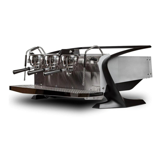
- Page 1 USER MANUAL VERSION 1.1 SEPTEMBER 2018 SLAY E R STE A M EP U S ER MA N UA L V1 .1 | S E P TE MB E R 1 1 , 201 8...
- Page 2 Information contained herein is subject to change without notice. Every precaution has been taken in the preparation of this manual; nevertheless, Slayer assumes no responsibility for errors or omissions or any damages resulting from the use of this information.
-
Page 3: Table Of Contents
Step 6: Turn On Elements Fast Clean I ’M R E A DY, LE T’S B R EW THI S! PARTS DI AG RA MS Using Slayer Steam EP Espresso Basics Factory Settings The Barista Dashboard™ SLAY E R STE A M EP U S ER MA N UA L V1 .1 | S E P TE MB E R 1 1 , 201 8... - Page 4 Steam Slayer Steam EP highlights the ease of use in push button volumetric Box Set, Steam EP celebrates what actuation and a mission to give the owner a total value in form and function.
- Page 5 For everything else, contact your authorized Slayer reseller or the appropriate party listed below. STOP N OT E FRO M O U R C U STO M ER SUCC ESS DI R EC TO R,...
- Page 6 Warranty coverage does not include parts that are subject to normal wear merchantability, and fitness for a particular purpose. and tear, as determined by Slayer. These include, but are not limited to, Warranty claims must be authorized by a Slayer Support representative shower screens, portafilter gaskets, expansion or anti-suction valves, and prior to repair or remedial action.
- Page 7 Using your machine outside of its defined before installing and operating your Slayer espresso machine. Incorrect functionality – as it is described in the “Using Slayer” section on page installation and operation may result in damage to the equipment, #17 of this guide –...
- Page 8 TDS levels to determine what produces your preferred taste. Calcium Carbonate: a dissolved mineral that determines the “hardness” All Slayer espresso machines need to be connected to a carbon water or “softness” of water. The desirable range of hardness is 4-5 grains.
-
Page 9: Recommended Tools & Accessories
• Pick or awl • Pliers • 9/16 inch socket wrench • Adjustable wrench • Slayer Espresso Machine Cleaner • Steam wand cleaner • Non-abrasive surface cleaner • Slayer Lubricant • Teflon tape SLAY E R STE A M EP U S ER MA N UA L V1 .1 | S E P TE MB E R 1 1 , 201 8... -
Page 10: Installation
INSTALLATION Only qualified service personnel should install Slayer espresso machines. For a list of certified Slayer technicians near you please contact our support department. Incorrect installation may result in injury and/or damage to the equipment. Please read the “Safety Advisory” on page #7 before beginning installation. -
Page 11: Step 1: Prepare Site
Read “Water Treatment Requirements” on page #8 for information about avoiding and addressing water-related issues. Your Slayer Steam machine needs to be installed on a structure that is capable of supporting its weight, including the weight of the water, once... -
Page 12: Step 2: Unpack Equipment
Your Slayer Steam EP machine will arrive in a lidded wooden crate, bolted body. To protect the machine during installation, keep all other to a pallet at the base. On the outside of the crate, a Steam EP Quick Start packing material in place. -
Page 13: Step 3: Connect Plumbing
STEP 3: CONNECT PLUMBING Your Slayer Steam EP machine will arrive with two (2) plumbing lines PRO CE D URE and two (2) drain hoses attached. One (1) additional plumbing line will arrive inside of the accessories box. A water treatment system is required, Install your water treatment system according to the instructions but not included. -
Page 14: Step 4: Connect Power
STEP 4: CONNECT POWER Your Slayer Steam machine will ship with the power configuration PRO CE D URE requested at the time of purchase. In most cases, this will include a plug end on the power cord. If your machine does not include a plug, do not Ensure that both steam actuators are in the “off”... -
Page 15: Step 5: Fill Tanks
STEP 5: FILL TANKS P RO CE D U R E Ensure that both steam actuators are in the “Off” position, the drain 5. Wait until the steam tank has filled completely, then fill the group hoses and water lines are connected, and the cup tray panels have heads by pressing the brew activation button “on”... -
Page 16: Step 6: Turn On Elements
STEP 6: TURN ON ELEMENTS P RO CE D U R E Ensure that all brew activation buttons are “OFF” (not lit or blinking), step. If no steam is produced, turn the main power On and Off; wait the cup tray panels have been removed, and the tanks have filled several minutes before repeating this step. -
Page 17: Using Slayer Steam Ep
These innovations will promote efficiency, accuracy, and comfort on every bar where Slayer Steam EP is found. Whether this is your first espresso machine or the latest in a long career, our instructions should serve as a helpful baseline for getting the most out of Steam EP. -
Page 18: Espresso Basics
– produces coffee with distinct characteristics that espresso prepared from dark-roasted coffee will more closely resemble contribute to discernible differences in beverage flavor. Slayer Steam is the characteristics of caramel, dark chocolate and nutty flavors. In some... - Page 19 Larger coffee dose (more weight): Recommended when espresso tastes bitter. • Increased flavor intensity To adjust the brew temperature, see instructions under Using Slayer > Adjust Brew Temperature on page #38. • Longer extraction time Recommended when espresso tastes sour, feels thin, extracts WATE R PRE SSURE quickly, or has no crema.
- Page 20 No one knows your coffee better than your roaster and in some cases you are still the best maestro for conducting great cup experiences. As a baseline Slayer recommends using a scale or graduated shot glasses to measure 25-40 grams or 1.0-1.5 fluid ounces of espresso per serving.
-
Page 21: Factory Settings
SLAYER STEAM FACTORY SETTINGS SL AYER ST E AM FACTO RY S E TTIN GS Brew Tank Temperature 93° C (200° F) Brew Pump Pressure 9 bar Steam Tank Pressure 1.4 bar Volumetrics Button 1 / 2 30g / 45g... -
Page 22: The Barista Dashboard
THE BARISTA DASHBOARD™ Slayer Steam EP is equipped with a digital interface that displays the • During the initial setup, select and change the functions to a desired essential functions of the machine up front and center for your ease. - Page 23 3. Press the button again to accept a null password ME N U O PTIO N S 4. Scroll to select Manager, use any combination of numbers and letters The first level of navigation is the Default Display menu which houses followed by a space <...
- Page 24 4. Select to clean ALL groups and depress for Gp 1, Gp 2 and so forth to backflush groups individually. 2. Place all three parts in a solution bath of Slayer Espresso Machine Cleaner and hot water. Follow the recipe on the container for best 5.
- Page 25 Program Volumetrics Programming 6. Steam Boiler Pressure 7. Reset Counters The Slayer Steam EP has the options for four programmable volumetric settings, two per button and four per group. When activating your 8. Passwords volumetrics, buttons 1 and 2 pressed once and will showcase the first layer of stored volumetrics.
- Page 26 9. At this point all brew button lights will blink again prompting the user via the Copy to All Groups YES/NO feature. to select the next button and program a value. The volumetrics are measured by a number that is related to the 10.
- Page 27 NOTE: Programming the brew volume does not affect your preinfusion PROTIP: For an effective wetting and hold cycle you must choose a pre- settings however it will affect your extraction. Adjust the grind wet and hold value otherwise the extraction will proceed as a normal shot, accordingly.
-
Page 28: Prepare Espresso
PREPARE ESPRESSO Slayer Steam EP utilizes a classic “9-bar” extraction method to produce PRO CE D URE espresso in a system with custom gicleurs and precision screens. Each brew button allows for two presets in a value range of 20—1000 or M for The following steps represent a good starting point when first using Slayer manual. -
Page 29: Steam Milk
8. Wipe the steam wand with a damp cloth, removing all milk residue, then purge again to remove any milk residue inside the wand. The following steps represent a good starting point when first using Slayer Steam to prepare milk. -
Page 30: Adjust Brew Pump Pressure
ADJ U ST B R E W PU M P PR ESSUR E ADJUST H OT WATE R TE MPE RATURE Slayer Steam features a blending valve that draws water from the steam I NC LU DE D PA RTS tank and main cold water line simultaneously. -
Page 31: Use Hot Water Tap
USE HOT WATER TAP Slayer Steam features a blended hot water valve that draws from the Adjusting this value can increase the pressure in which the steam exits the steam tank and main cold water line. The hot water tap is located on the steam wand. -
Page 32: Advanced Menu: Password Protected Option
5. Repeat steps 4-5 for all remaining settings: Do not interact with the Advanced Menu before reading this manual in its entirety. Then – if unsure – consult your Slayer representative, • Gp1 (heating element for leftmost brew tank) reseller, or qualified service personnel. - Page 33 5. Press and release the jog wheel to confirm your new setting and L IF E TI ME CO U NT (SH OT CO UNT ER ) proceed to the next step. The option to adjust the hour will be presented.
- Page 34 IMPORTANT: To configure the offsets, you must have a scace device or From the Home Menu, scroll to Passwords and enter the Advanced defer to a certified Slayer technician. This can NOT be performed with Menu password. hand held temperature probes.
- Page 35 6. From the Home menu, scroll to Password and enter the Advanced menu access password Slayer Steam EP is equipped with three layers of programming and usage 7. Scroll to “FlowMeter Calib.”, depress to enter the menu through the Barista Dashboard™. The factory passwords are simply set at <null>...
- Page 36 4. Select the option <OFF>. breakdowns and extensive repairs. The Slayer Steam EP alerts you via a 5. Press and hold (2 seconds) to save and exit back to the Advanced countdown clock of when your next suggested Preventative Maintenance menu or long hold (5 seconds) to exit to the Home Menu.
-
Page 37: Adjust Shot Volumes
ADJUST BREW PUMP PRESSURE ADJUST SHOT VOLUMES Slayer Steam features automatic-volumetric operation, which is based I NC LU DE D PA RTS on readings from the flow meter. The left group screen is the main menu for all machine adjustments. Additionally, each group head has two (2) •... -
Page 38: Adjust Brew Tank Temperature
ADJUST BREW TANK ADJUST STEAM TANK PRESSURE TEMPERATURES At the factory, the steam tank temperature is set to 1.4 bar (25 psi). Adjust the steam tank temperature with the following steps. At the factory, the brew tank temperatures are set to 93° C (200° F). Adjust the brew tank temperatures with the following steps. -
Page 39: Adjust Hot Water Dose
Slayer Steam utilizes a timer to dispense pre-configured volumes of hot water. Adjust the hot water dose with the following steps. Slayer Steam features a blending valve that draws water from the steam tank and main cold water line simultaneously. Custom water temperatures P RO CE D U R E are configured with the blending valve. -
Page 40: Other Menu Options
S ET LAN G UAGE not interact with the Advanced Menu before reading this manual in its entirety, then – if unsure – consulting your Slayer representative, reseller, Press and hold the jog wheel above the left group head for five or qualified service personnel. - Page 41 Cleaning & Preventative Maintenance Keeping your machine clean and properly maintained is essential to ensuring espresso quality and equipment longevity. Espresso machines require both daily cleaning and ongoing periodic maintenance. The frequency with which these tasks should be completed will depend on the location and use of your espresso machine.
-
Page 42: Clean The Machine Exterior
CLEAN THE MACHINE EXTERIOR GENERAL GROUP HEAD CARE Use a soft, clean towel to wipe the surfaces of the machine. Do not use Regular cleaning and backflushing optimizes machine performance and abrasive cleaners. Small amounts of window cleaner may be used on glass espresso flavor by preventing the buildup of coffee oils. -
Page 43: Backflush The Group Heads
BACKFLUSH THE GROUP HEADS Through the Barista Dashboard, Slayer Steam automates backflush cycles 3. Remove portafilter baskets and portafilter springs from all for each group head. Backflush with an approved espresso machine portafilter bodies. cleaning powder at least once daily. Complete the “Fast Clean” procedure 4. - Page 44 Basic Backflushing Steps SLAY E R STE A M EP U S ER MA N UA L V1 .1 | S E P TE MB E R 1 1 , 201 8...
-
Page 45: Fast Clean
FAST CLEAN Designed to be done without the use of detergent after the busy portion PRO CE D URE of the day, at the shift change or when changing out the coffees in the hopper. Leave the screen, screw in place. Complete the following steps for Remove portafilter from group head, then use a cleaning brush to each group head whenever your machine requires minor cleaning. - Page 46 Only qualified service personnel should repair Slayer Espresso machines. Incorrect repair may result in injury and/ or damage to the equipment. Please consult your distributor for a qualified Slayer service technician.
-
Page 47: Brew Group Head Components
BREW GROUP HEAD COMPONENTS ITEM NO. PART NUMBER DESCRIPTION QTY. 44000-36063 FHMS,1/4-20X0.38,PHILLIPS,18-8 SS SLAY E R STE A M EP U S ER MA N UA L V1 .1 | S E P TE MB E R 1 1 , 201 8 20000-16081 GROUP COVER, CLOSED TOP 44005-20120... - Page 48 BREW GROUP HEAD COMPONENTS I T E M N O. PART NU M BER DESC R IPT IO N QTY. 44000-36063 FHMS,1/4-20X0.38,PHILLIPS,18-8 SS 20000-16081 GROUP COVER, CLOSED TOP 44005-20120 STANDOFF,0.5 DIA,1/4-20X0.63,F,NYLON 42000-34300 BLEED SCREW PLUG 44005-20110 THRD ROD,1/4-20X0.50,18-8 SS 10000-16051 GROUP CAP 46000-50100 GROUP CAP PAPER GASKET...
-
Page 49: Brew Tank Assembly
BREW TANK ASSEMBLY ITEM PART NUMBER DESCRIPTION 44000-36080 3/8-16 NUT 44000-36070 3/8 LOCK WASHER 30000-20130 600 WATT BREW TANK ELEMENT 30000-20140 ELEMENT GASKET 30000-20251 THERMOSTAT,110C 44005-10090 SHCS,M4-0.7X12MM,18-8 SS 30000-20153 3-WAY SOLENOID VALVE, 2mm, FORGED FLANGE, 24VDC 46000-10040 O-RING,FKM,DASH NO. -010 42000-34300 BLEED SCREW PLUG 15005-16061... - Page 50 BREW TANK ASSEMBLY I T E M N O. PART NU M BER DESC R IPT IO N 44000-36080 3/8-16 NUT 44000-36070 3/8 LOCK WASHER 30000-20130 600 WATT BREW TANK ELEMENT 30000-20140 ELEMENT GASKET 30000-20251 THERMOSTAT,110C 44005-10090 SHCS,M4-0.7X12MM,18-8 SS 30000-20153 3-WAY SOLENOID VALVE, 2mm, FORGED FLANGE, 24VDC 46000-10040 O-RING,FKM,DASH NO.
-
Page 51: Steam Tank Assembly
FITTING, 1/4" TUBE OD X 1/8" NPTF - M, BRASS 40005-32170 STEAM PRV TUBE 15005-12110 STEAM TANK, SLAYER STEAM, 2 GROUP 15005-13110 STEAM TANK, SLAYER STEAM, 3 GROUP 42000-34680 FITTING, EASY-ALIGN, COMPRESSION TUBE, 5/16" OD TUBE X 1/4" M PIPE, BRASS... - Page 52 FITTING, 1/4" TUBE OD X 1/8" NPTF - M, BRASS 40005-32170 STEAM PRV TUBE 15005-12110 STEAM TANK, SLAYER STEAM, 2 GROUP 15005-13110 STEAM TANK, SLAYER STEAM, 3 GROUP 42000-34680 FITTING, EASY-ALIGN, COMPRESSION TUBE, 5/16" OD TUBE X 1/4" M PIPE, BRASS...
-
Page 53: Steam & Hot Water Valve Train
PART NUMBER DESCRIPTION 40015-32007 STEAM ACTUATOR TO LEFT WAND TUBE, STEAM BASIC 40005-32110 FLOW METER TUBE 99015-10001 STEAM SOLENOID ASSEMBLY,L,STEAM EP 40015-32003 STEAM TANK TO ACTUATOR TUBE, STEAM BASIC 40015-32010 LTEK PRESSURE TRANSDUCER TUBE, STEAM 99005-17010 PRESSURE TRANSDUCER ASSEMBLY, ELTEK... - Page 54 DESC R IPT IO N 40015-32007 STEAM ACTUATOR TO LEFT WAND TUBE, STEAM BASIC 40005-32110 FLOW METER TUBE 99015-10001 STEAM SOLENOID ASSEMBLY,L,STEAM EP 40015-32003 STEAM TANK TO ACTUATOR TUBE, STEAM BASIC 40015-32010 LTEK PRESSURE TRANSDUCER TUBE, STEAM 99005-17010 PRESSURE TRANSDUCER ASSEMBLY, ELTEK...
-
Page 55: Steam Wand Assembly
SLAY E R STE A M EP U S ER MA N UA L V1 .1 | S E P TE MB E R 1 1 , 201 8 46005-53170 GRIP, STEAM WAND, COOL TOUCH 40015-50330 STEAM WAND, COOL TOUCH, SLAYER STEAM, EP... - Page 56 I T E M N O. PART NU M BER DESC R IPT IO N 46005-53170 GRIP, STEAM WAND, COOL TOUCH 40015-50330 STEAM WAND, COOL TOUCH, SLAYER STEAM, EP 10005-10008 STEAM AND HOT WATER LOCK NUT 10005-10002 STEAM, WAND SOCKET 46005-53110...
-
Page 57: Hot Water Wand Assembly
HOT WATER WAND ASSEMBLY ITEM PART NUMBER DESCRIPTION 46005-53170 GRIP, STEAM WAND, COOL TOUCH 40004-50450 HOT WATER WAND, HOME MACHINE SLAY E R STE A M EP U S ER MA N UA L V1 .1 | S E P TE MB E R 1 1 , 201 8 46000-50030 O RING FOR STEAM TIP, 1.5 X 6 46000-50350... - Page 58 HOT WATER WAND ASSEMBLY I T E M N O. PART NU M BER DESC R IPT IO N 46005-53170 GRIP, STEAM WAND, COOL TOUCH 40004-50450 HOT WATER WAND, HOME MACHINE 46000-50030 O RING FOR STEAM TIP, 1.5 X 6 46000-50350 HOT WATER SPOUT 46000-53050...
-
Page 59: Steam Actuator Assemblies
STEAM ACTUATOR ASSEMBLIES LEFT LEFT RIGHT ITEM PART NUMBER DESCRIPTION RIGHT 44000-36102 BOLT, HEX HEAD, 1/4-20 X 3/4 44005-10320 PLASTIC STEAM ACTUATOR DISK SPRING 99015-10004 LEFT ACTUATOR HANDLE ASSEMBLY 44000-36260 ACTUATOR, STEAM, STOP BOLT, SHORT ITEM PART NUMBER DESCRIPTION 46005-01010 TEFLON GASKET 13005-30045 CHASSIS BRACE LEFT FRONT, STEAM... - Page 60 STEAM ACTUATOR ASSEMBLIES I T E M N O. PART NU M BER DESC R IPT IO N 44000-36102 BOLT, HEX HEAD, 1/4-20 X 3/4 44005-10320 PLASTIC STEAM ACTUATOR DISK SPRING 99015-10004 LEFT ACTUATOR HANDLE ASSEMBLY 44000-36260 ACTUATOR, STEAM, STOP BOLT, SHORT 46005-01010 TEFLON GASKET 13005-30045...
-
Page 61: Water Fill Circuit
FITTING, EASY-ALIGN, COMPRESSION TUBE, STRAIGHT ADAPTER FOR 1/4" TUBE OD X 1/4 - M PIPE, BRASS 40005-32110 FLOW METER TUBE 40005-32010 WATER INLET TUBE, SLAYER STEAM, GROUP 3 (3 GROUP ONLY] 40005-32020 WATER INLET TUBE, SLAYER STEAM, GROUP 2 SLAY E R STE A M EP U S ER MA N UA L V1 .1 | S E P TE MB E R 1 1 , 201 8... - Page 62 FITTING, EASY-ALIGN, COMPRESSION TUBE, STRAIGHT ADAPTER FOR 1/4" TUBE OD X 1/4 - M PIPE, BRASS 40005-32110 FLOW METER TUBE 40005-32010 WATER INLET TUBE, SLAYER STEAM, GROUP 3 (3 GROUP ONLY] 40005-32020 WATER INLET TUBE, SLAYER STEAM, GROUP 2 40005-32030 WATER INLET TUBE, SLAYER STEAM, GROUP 1 42000-34500 FITTING, 1/4"...
-
Page 63: Drain Circuit
DRAIN CIRCUIT ITEM PART NUMBER DESCRIPTION 42000-34560 FITTING, 90 DEG ELBOW FOR 1/4" TUBE OD X 1/8" NPTF - M, BRASS 40005-32060 HOT WATER TO MIX VALVE TUBE 40015-32009 STEAM ACTUATOR DRAIN TUBE, LEFT 42000-34810 3/16" TUBE X 1/8" MALE NPT BRASS COMPRESSION CONNECTOR 40000-32150 HIGH-TEMPERATURE SILICONE RUBBER TUBING, SOFT, 5/16"... - Page 64 DRAIN CIRCUIT I T E M N O. PART NU M BER DESC R IPT IO N 42000-34560 FITTING, 90 DEG ELBOW FOR 1/4" TUBE OD X 1/8" NPTF - M, BRASS 40005-32060 HOT WATER TO MIX VALVE TUBE 40015-32009 STEAM ACTUATOR DRAIN TUBE, LEFT 42000-34810 3/16”...
-
Page 65: Display Assembly
MOMENTARY PUSH BUTTON, HOT WATER, WIRED 44005-10140 SCREW,TRUSS HD,EXTRA WD,M4-0.7X6MM,PHILLIPS,18-8 SS 30005-10120 DISPLAY INTERFACE CABLE, 200mm 44005-10211 FHMS,M4-0.7X8MM,PHILLIPS,18-8 SS 30005-60110 OLED DISPLAY ASSEMBLY, SLAYER STEAM 30005-03010 OPTICAL ENCODER 20005-10001 FACE PLATE 46005-21010 VHB ON BACKING BOARD FOR DISPLAY SCREEN 26005-10000... - Page 66 MOMENTARY PUSH BUTTON, HOT WATER, WIRED 44005-10140 SCREW,TRUSS HD,EXTRA WD,M4-0.7X6MM,PHILLIPS,18-8 SS 30005-10120 DISPLAY INTERFACE CABLE, 200mm 44005-10211 FHMS,M4-0.7X8MM,PHILLIPS,18-8 SS 30005-60110 OLED DISPLAY ASSEMBLY, SLAYER STEAM 30005-03010 OPTICAL ENCODER 20005-10001 FACE PLATE 46005-21010 VHB ON BACKING BOARD FOR DISPLAY SCREEN 26005-10000...
-
Page 67: Electronics Components
ELECTRONICS COMPONENTS ITEM NO. PART NUMBER DESCRIPTION 30005-20270 2 POLE ROCKER BREAKER SWITCH 2 GROUP MACHINES ONLY 30000-20230 BREAKER,30A,2POLES 3 GROUP MACHINES ONLY 30000-20240 BREAKER, 40A, 2 POLES 13005-20027 ELECTRICAL SHIELD ASSEMBLY, STEAM, 2 GROUP 13005-30027 ELECTRICAL SHIELD, ASSEMBLY, STEAM, 3 GROUP 44004-36140 SCREW, PAN HEAD PHILLIPS, M3 SIZE, 20mm LENGTH, .5mm PITCH, STAINLESS SLAY E R STE A M EP U S ER MA N UA L V1 .1 | S E P TE MB E R 1 1 , 201 8... - Page 68 ELECTRICAL SHIELD, ASSEMBLY, STEAM, 3 GROUP 44004-36140 SCREW, PAN HEAD PHILLIPS, M3 SIZE, 20mm LENGTH, .5mm PITCH, STAINLESS 44005-10130 PHMS,M4-0.7X8MM,PHILLIPS,18-8 SS 44005-10370 SCREW,M4-0.7X16.0,PHMS,PHILLIPS,18-8 30005-10080 MAIN BRAIN, SLAYER STEAM 30000-20003 POWER SUPPLY, COSEL, 500 WATT 44005-10390 SCREW,M3-0.5X8.0,PHMS,PHILLIPS,18-8 10005-20005 SUB PLATE, STEAM 30000-20011...
-
Page 69: Panels, Rails & Wings
BACK PANEL, STEAM, 3GP, CLEAR ANODIZED 46000-50180 RUBBER FOOT, SLAYER STEAM SLAY E R STE A M EP U S ER MA N UA L V1 .1 | S E P TE MB E R 1 1 , 201 8... - Page 70 CUP TRAY RAIL CLIP, LEFT, STEAM, 2 GROUP 13005-20090-75 BACK PANEL, STEAM, 2GP, CLEAR ANODIZED 13005-30090-75 BACK PANEL, STEAM, 3GP, CLEAR ANODIZED 46000-50180 RUBBER FOOT, SLAYER STEAM 20205-10000-74 WING SUPPORT, RIGHT, STEAM -P000-BK247 FLAT BLACK 44000-36064 FHMS,M5-0.8X10MM,PHILLIPS,18-8 SS 13005-30015-75 SIDE PANEL, RIGHT REAR, STEAM, CLEAR ANODIZED...
-
Page 71: Drip Trays & Cup Trays
DRIP TRAYS & CUP TRAYS ITEM NO. PART NUMBER DESCRIPTION 13005-30034 CUP TRAY COVER, LEFT, STEAM (for 3 Group Only) 13005-30035 CUP TRAY COVER, CENTER, STEAM 13005-20029 CUP TRAY, STEAM, 2GP 13005-30029 CUP TRAY, LOWER, STEAM, 3GP 13005-30033 CUP TRAY COVER, RIGHT, STEAM 13015-16001 DRIP TRAY BRACKET, STEAM BASIC, RIGHT 13005-20038... - Page 72 DRIP TRAYS & CUP TRAYS I T E M N O. PART NU M BER DESC R IPT IO N 13005-30034 CUP TRAY COVER, LEFT, STEAM 13005-30035 CUP TRAY COVER, CENTER, STEAM (for 3 Group Only) 13005-20029 CUP TRAY, STEAM, 2GP 13005-30029 CUP TRAY, LOWER, STEAM, 3GP 13005-30033...
-
Page 73: Pump Assembly & Lines
PUMP ASSEMBLY & LINES ITEM NO. PART NUMBER DESCRIPTION 30000-20470 HARNESS, MOTOR, 2/3 GROUP,UL 30000-20446 HARNESS, MOTOR, 2/3 GROUP,CE 30000-58020 PUMP MOTOR 44000-58010 V BAND CLAMP SLAY E R STE A M EP U S ER MA N UA L V1 .1 | S E P TE MB E R 1 1 , 201 8 40005-10010 STAINLESS STEEL HOSE, 3/8"... - Page 74 42000-10060 REDUCER, 3/8" - M X 1/8" - F 46000-50320 BREW GAUGE, 20BAR, CUSTOM PRINTED SLAYER LOGO. SCALE IN BAR. 30000-58030 PUMP, 45 GPH SLAY E R STE A M EP U S ER MA N UA L V1 .1 | S E P TE MB E R 1 1 , 201 8...
- Page 75 PORTAFILTERS ITEM PART NUMBER DESCRIPTION 46000-56100 PORTAFILTER, BLIND 46000-56551 SINGLE BASKET, RIDGELESS 46000-56552 DOUBLE BASKET, STEAM 46000-56080 TRIPLE PORTAFILTER BASKET, RIDGELESS SLAY E R STE A M EP U S ER MA N UA L V1 .1 | S E P TE MB E R 1 1 , 201 8 46000-56160 PORTAFILTER LOCKING SPRING, 1.20 mm, STAINLESS 46000-56120...
- Page 76 PORTAFILTERS I T E M N O. PART NU M BER DESC R IPT IO N 46000-56100 PORTAFILTER, BLIND 46000-56551 SINGLE BASKET, RIDGELESS 46000-56552 DOUBLE BASKET, STEAM 46000-56080 TRIPLE PORTAFILTER BASKET, RIDGELESS 46000-56160 PORTAFILTER LOCKING SPRING, 1.20 mm, STAINLESS 46000-56120 SPOUTED PORTAFILTER BODY ONLY 46000-56130 DOUBLE SPOUT...
-
Page 77: Wire Map
WIRE MAP 2- GRO U P MACH I NES SSR-BG2 SSR-BG1 CN12 CN18 CN20 CN26 CN28CN32 CN34 CN38 CN40CN44 CN46 CN47 CN19 CN21 CN27 CN29 CN45 CN48 CN49 CN13 CN16 CN22CN24 CN42 CN14 CN17 CN23CN25 CN30 CN31 CN36 CN39 CN43 SSR-STM 2 GROUP MACHINES CONNECTION... - Page 78 WIRE MAP: 2-GROUP MACHINES connection position wire color G RO U P 1 connection position wire color SHORT BREW SW. CN14 YELLOW GROUND GREEN BLACK/MAROON FLOW MTR GND BLACK LONF BREW SW. WHITE FLOW MTR +10Vdc CN10 BLACK/WHITE HOT WATER SW. CN11 VIOLET/BLACK STEAM SW.
- Page 79 WIRE MAP: 3-GROUP MACHINES G RO U P 1 connection position wire color connection position wire color SHORT BREW SW. CN14 YELLOW GROUND GREEN BLACK/MAROON FLOW MTR GND BLACK LONF BREW SW. WHITE FLOW MTR +10Vdc CN10 BLACK/WHITE HOT WATER SW. CN11 VIOLET/BLACK SHORT LED...
Need help?
Do you have a question about the STEAM EP and is the answer not in the manual?
Questions and answers