Table of Contents
Advertisement
Quick Links
Advertisement
Table of Contents

Related Manuals for Varian 990 CLD Autoline


Summary of Contents for Varian 990 CLD Autoline
- Page 1 Artisan Technology Group is your source for quality new and certified-used/pre-owned equipment SERVICE CENTER REPAIRS WE BUY USED EQUIPMENT • FAST SHIPPING AND DELIVERY Experienced engineers and technicians on staff Sell your excess, underutilized, and idle used equipment at our full-service, in-house repair center We also offer credit for buy-backs and trade-ins •...
- Page 2 990 CLD Autoline™ INSTRUCTION MANUAL Leak Detector Manual N0. 6999-09-690 Revision L February 2004 Artisan Technology Group - Quality Instrumentation ... Guaranteed | (888) 88-SOURCE | www.artisantg.com...
- Page 3 990 CLD Autoline™ Leak Detector Copyright 2004 Vacuum Technologies Artisan Technology Group - Quality Instrumentation ... Guaranteed | (888) 88-SOURCE | www.artisantg.com...
- Page 4 990 CLD Autoline™ Leak Detector Warranty Products manufactured by Seller are warranted against defects in materials and workmanship for twelve (12) months from date of shipment thereof to Customer, and Seller’s liability under valid warranty claims is limited, at the option of Seller, to repair, to replace, or refund of an equitable portion of the purchase price of the Product.
- Page 5 990 CLD Autoline™ Leak Detector This page intentionally left blank. Artisan Technology Group - Quality Instrumentation ... Guaranteed | (888) 88-SOURCE | www.artisantg.com...
-
Page 6: Table Of Contents
990 CLD Autoline™ Leak Detector Table of Contents Declaration of Conformity Preface ............................xiv Hazard and Safety Information ....................xiv 990 CLD Leak Detector Hazards ....................xv 990 CLD Leak Detector Factory Calibration Data ..............xvii Section 1. Introduction ......................... 1-1 Model Types ..........................1-2 OPTO-22 Modules........................ - Page 7 990 CLD Autoline™ Leak Detector Section 4. Maintenance ........................ 4-1 Daily Maintenance ........................4-3 Leak Detector Sensitivity Check .................... 4-3 Annual Maintenance – Complete Overhaul ................4-3 As-Required Maintenance......................4-4 Removing, Cleaning, and Re-installing the Spectrometer Tube..........4-5 Enhancement Magnet Adjustment ..................4-8 Ion Source Replacement .......................
- Page 8 990 CLD Autoline™ Leak Detector Appendix A. Understanding the 990 CLD Analog Leak Rate Output ........A-1 Understanding the 990 CLD Analog Leak Rate Output ...............A-1 Linear Analog Voltage Output....................A-1 Why Use a Linear Analog Output? ..................A-2 Logarithmic Analog Output Voltage ..................A-3 Why Use Logarithmic Analog Output Voltage? ..............A-4...
- Page 9 990 CLD Autoline™ Leak Detector This page intentionally left blank. Artisan Technology Group - Quality Instrumentation ... Guaranteed | (888) 88-SOURCE | www.artisantg.com...
- Page 10 990 CLD Autoline™ Leak Detector List of Figures Figure Caption Page 990 CLD Leak Detector ....................... 1-1 Signal Flow Diagram......................1-5 Primary Operating Controls and Indicators, 990 CLD Leak Detector........1-6 Secondary Operating Controls and Indicators, 990 CLD Leak Detector........ 1-8 Rear Panel, 990 CLD Leak Detector...................
- Page 11 990 CLD Autoline™ Leak Detector This page intentionally left blank. Artisan Technology Group - Quality Instrumentation ... Guaranteed | (888) 88-SOURCE | www.artisantg.com...
- Page 12 990 CLD Autoline™ Leak Detector List of Tables Table Title Page 990 CLD Leak Detector Component Parts................1-2 900 CLD Customized Configuration ..................1-2 OPTO–22 Module Part Numbers ..................1-3 Primary Operating Controls and Indicators ................1-7 Secondary Operating Controls and Indicators ..............1-9 Rear Panel Inputs and Outputs...................
- Page 13 990 CLD Autoline™ Leak Detector This page intentionally left blank. Artisan Technology Group - Quality Instrumentation ... Guaranteed | (888) 88-SOURCE | www.artisantg.com...
-
Page 14: Declaration Of Conformity
990 CLD Autoline™ Leak Detector to which this declaration relates is in conformity with the following standard(s) or other normative documents. auf das sich diese Erklärung bezieht, mit der/den flogenden Norm(en) oder Richtlinie(n) übereinstimmt. -
Page 15: Preface
990 CLD Autoline™ Leak Detector Preface Hazard and Safety Information This manual uses the following standard safety protocols: Warnings are used when failure to observe instructions or WARNING precautions could result in injury or death. Cautions are used when failure to observe instructions could... -
Page 16: 990 Cld Leak Detector Hazards
990 CLD Autoline™ Leak Detector 990 CLD Leak Detector Hazards This product must only be operated and maintained by trained personnel. Before operating or servicing equipment, read and thoroughly understand all operation/ maintenance manuals provided by Vacuum Technologies. Be aware of the hazards associated with this equipment, know how to recognize potentially hazardous conditions, and how to avoid them. - Page 17 990 CLD Autoline™ Leak Detector Where applicable, inspect for any damage to retaining rings NOTE and O-rings. Remove them carefully with your fingers. Do not use any metal tools for this task. This prevents scratching of any sealing surfaces. To clean O-rings, wipe them with a clean, lint-free cloth or NOTE paper.
-
Page 18: 990 Cld Leak Detector Factory Calibration Data
990 CLD Autoline™ Leak Detector 990 CLD Leak Detector Factory Calibration Data Model Number ______________________________ Date ___________________________________ Serial Number _______________________________ Initials _________________________________ The Vacuum Technologies 990 CLD leak detector is thoroughly tested prior to shipment. It is shipped tuned to helium on Filament No. 1. Normally, once set, the tuning adjustments are left untouched and calibration is verified as required. - Page 19 990 CLD Autoline™ Leak Detector This page intentionally left blank. Artisan Technology Group - Quality Instrumentation ... Guaranteed | (888) 88-SOURCE | www.artisantg.com...
-
Page 20: Section 1. Introduction
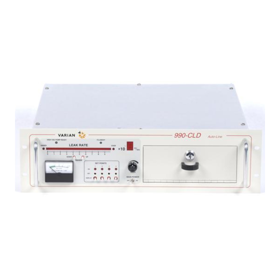
This manual covers the description, installation, operation, theory, and maintenance of the Vacuum Technologies 990 CLD AutoLine™ leak detector (Figure 1-1 on page 1-1). The 990 CLD leak detector is a modular, mass spectrometer leak detector that uses helium as the trace gas. -
Page 21: Model Types
990 CLD Autoline™ Leak Detector Model Types The basic 990 CLD leak detector (PN L990000000120) is equipped with the components listed in Table 1-1. Table 1-1 990 CLD Leak Detector Component Parts Description Part Number Main Electronics Console L9022301, 302, or 303, 120 V Control Input... -
Page 22: Opto-22 Modules
990 CLD Autoline™ Leak Detector OPTO-22 Modules Spare OPTO-22 modules for 120 VAC units, or for input control voltages other than 120 VAC, can be ordered as listed in 1-3. Table 1-3 OPTO–22 Module Part Numbers Vacuum Technologies Mfr. Part No. -
Page 23: Signal Flow
990 CLD Autoline™ Leak Detector Signal Flow The electrical signal that represents the concentration of helium in the vacuum system originates in the spectrometer tube preamplifier (Figure 1-2 on page 1-5). Also, refer to “High Vacuum System” on page 1-14. - Page 24 990 CLD Autoline™ Leak Detector Figure 1-2 Signal Flow Diagram Artisan Technology Group - Quality Instrumentation ... Guaranteed | (888) 88-SOURCE | www.artisantg.com...
-
Page 25: Physical Description
990 CLD Autoline™ Leak Detector Physical Description The physical components of the 990 CLD leak detector include: ❑ “Controls and Indicators” ❑ “Internal Components” on page 1-13 Controls and Indicators The spectrometer tube and high vacuum pump are mounted together on a bracket with proper couplings to simplify customer mounting and are connected to the main electronics console by electrical cables. - Page 26 990 CLD Autoline™ Leak Detector Table 1-4 Primary Operating Controls and Indicators Item Control/Indicator Function LEAK RATE Display Bar graph display. Indicates leak rate in std cc/sec. Over-scale and under-scale conditions are indicated by LEDs at the right and left of this display, respectively.
- Page 27 990 CLD Autoline™ Leak Detector Secondary Controls Figure 1-4 Secondary Operating Controls and Indicators, 990 CLD Leak Detector Table 1-5 describes the Secondary Operating Controls and Indicators, which are used mainly for tuning and calibration purposes. Refer to Figure 1-4 and Figure 1-5 on page 1-10.
- Page 28 990 CLD Autoline™ Leak Detector Table 1-5 Secondary Operating Controls and Indicators Item Control/Indicator Function SENSITIVITY HI/LOW Toggle switch that changes the speed of the high vacuum pump. It is used to change the sensitivity of the leak detector by a factor of ten.
- Page 29 990 CLD Autoline™ Leak Detector Rear Panel Inputs and Outputs Figure 1-5 Rear Panel, 990 CLD Leak Detector Table 1-6 Rear Panel Inputs and Outputs Item Description Input/ Function Output REMOTE SPEAKER Jack Jack for external speaker. The loudspeaker should have an internal impedance between 4 and 8 Ohms, and a 5 W minimum power capability.
- Page 30 990 CLD Autoline™ Leak Detector Table 1-6 Rear Panel Inputs and Outputs (Continued) Item Description Input/ Function Output HIGH VACUUM PUMP Pluggable terminal block for connections to the Connector high vacuum pump. See “Wire Run Lists” on page 2-4. OPTO-22 Modules...
- Page 31 990 CLD Autoline™ Leak Detector Table 1-6 Rear Panel Inputs and Outputs (Continued) Item Description Input/ Function Output 9-18, 9-19, 9-20 SET MODE ACTIVE Relay contact closes when any of the four SET POINT SET buttons are pressed. SET POINTS Connector Pluggable terminal block for connections to set point relays.
-
Page 32: Internal Components
990 CLD Autoline™ Leak Detector Internal Components Internal components consist of: ❑ “Sub–assembly Level Items” ❑ “High Vacuum System” Sub–assembly Level Items Internally, the 990 CLD leak detector (Figure 1-6) is comprised of electronic subassemblies, power and control transformers, and interconnecting cabling. All subassemblies are user replaceable. - Page 33 990 CLD Autoline™ Leak Detector High Vacuum System The high vacuum system serves three functions, it: ❑ Maintains the required vacuum in the spectrometer tube, ❑ Connects the customer’s part or system to the spectrometer tube. ❑ Removes helium after a test.
- Page 34 990 CLD Autoline™ Leak Detector Spectrometer Tube The spectrometer tube is the heart of the leak detector. The spectrometer tube and the leak rate indicator shown in Figure 1-7 provide a visual representation of the helium concentration in the vacuum system.
- Page 35 990 CLD Autoline™ Leak Detector Ion Source The ion source consists of two filaments, two halves of an ion chamber, a pair of focus plates, and a grounded exit slit (the exit slit is a reZmovable part of the spectrometer tube). The top half of the...
-
Page 36: Section 2. Customer Integration
990 CLD Autoline™ Leak Detector Section 2. Customer Integration This section contains instructions for unpacking, inspecting, and installing the Vacuum Technologies 990 CLD leak detector. Also included are instructions for setting up the leak detector prior to actual operation. The rack-mounted 990 CLD leak detector is intended for applications in which the leak detector components are permanently mounted. -
Page 37: Leak Detector Location And Required Services
990 CLD Autoline™ Leak Detector Leak Detector Location and Required Services Vacuum Technologies recommends the use of either its SD-90, SD-200, SD-300, or SD-450 helium stable mechanical pumps. Do not use a pump that exhibits helium retention characteristics which cause high background. -
Page 38: Electrical Connections
990 CLD Autoline™ Leak Detector Electrical Connections For this procedure, refer to Figure 1-1 on page 1-1, Figure 1-3 on page 1-6 through Figure 1-5 on page 1-10. Electrical connections include spectrometer tube, high vacuum pump, spectrometer tube integral ground, and ancillary connections. - Page 39 990 CLD Autoline™ Leak Detector ❑ A 6 A, 250 VAC, form C, dry contact provides an indication that the spectrometer tube pressure is low enough for proper operation. ❑ A 6 A, 250 VAC, form C, dry contact provides an indication that the filament is operating.
-
Page 40: Leak Rate Output Voltage Selection
990 CLD Autoline™ Leak Detector Leak Rate Output Voltage Selection The leak rate output voltage, on the 990 CLD leak detector rear panel, can be configured to vary linearly or logarithmically with the measured leak rate. For a logarithmic output format, either a 2 V/decade or 3 V/decade sensitivity is available (Figure 2-1). -
Page 41: Sensitivity
990 CLD Autoline™ Leak Detector Sensitivity During the process of installing the 990 CLD leak detector and building the associated vacuum system, determining the sensitivity of the system is necessary. The detector is able to measure four decades of leak rate signal. For example, in a typical system with the V70D MacroTorr pump running at high speed, the four decades of leak rate might be −7... - Page 42 990 CLD Autoline™ Leak Detector Table 2-3 Preamplifier Cable Wire Run List Octal Receptacle 15-pin Connector Function Pin No. (rear panel of Console) Pin No. Color RG-58 Center Suppressor Voltage +15V RG-58 Shield Ground (multi-conductor shield) −15V Offset 2 RG-174 Center...
-
Page 43: Dismounting The Leak Detector
990 CLD Autoline™ Leak Detector Dismounting the Leak Detector To disassemble the 990 CLD leak detector from the rack: 1. Shut down the leak detector. 2. Label and disconnect controller electrical connections. 3. Remove the leak detector carefully from the rack on the slides. -
Page 44: Section 3. Operations
990 CLD Autoline™ Leak Detector Section 3. Operations This section contains instructions for operating the 990 CLD leak detector. Due to the universality of the instrument, specific procedures for operating the leak detector vary according application. This section describes the features of the leak detector in detail and provides general operating guidelines to optimize the performance of the instrument. -
Page 45: Required Daily Procedures
990 CLD Autoline™ Leak Detector Required Daily Procedures Required daily procedures include: ❑ “Installation and Initial Setup Procedure” on page 3-2 ❑ “Tuning Adjustments and Calibration Check” on page 3-4 Installation and Initial Setup Procedure Complete this procedure at each startup: 1. - Page 46 990 CLD Autoline™ Leak Detector 6. When the spectrometer tube pressure meter indicates two-thirds of the way down in the green band (from right to left), move the FILAMENT switch on the secondary control panel to the ON/AUTO position. When the FILAMENT switch is in the ON/AUTO position, and the needle of the spectrometer tube pressure gauge reaches two-thirds of the way down the green band, the filament lights automatically.
-
Page 47: Tuning Adjustments And Calibration Check
990 CLD Autoline™ Leak Detector Tuning Adjustments and Calibration Check Each day, and as otherwise scheduled, properly tune the spectrometer tube helium sensitivity. This is generally done by using a standard reference leak of known value, called a calibrated leak. Two types of calibrated leaks are available: those with a helium reservoir* and those that operate on the capillary principle and require a helium source from the user. - Page 48 990 CLD Autoline™ Leak Detector If the bar graph ZERO control is set such that none of the segments on the bar graph illuminate, the corresponding UNDER scale LED illuminates. Adjust the ZERO control so that one segment is lit (with no helium or leak present). If the OVER scale LED illuminates (along the 50 bar graph segments), select a larger leak range.
- Page 49 990 CLD Autoline™ Leak Detector Tuning the Spectrometer Tube Using a Helium Reservoir Leak The calibrated leak can be used for two functions: ❑ Tuning the spectrometer tube ❑ Calibrating the leak detector These functions are normally performed at the same time, in the sequence indicated.
- Page 50 990 CLD Autoline™ Leak Detector Calibrating the Leak Detector Calibration the detector is normally performed after tuning the leak detector to helium. If calibration is attempted before verifying tuning, the calibration procedure may not be successful. The Minimum Detectable Leak (MDL) is a function of pumping speed, vacuum system architecture, and electrical noise level.
-
Page 51: As-Required Procedures
990 CLD Autoline™ Leak Detector To peak and calibrate the leak detector for a strong helium signal: Only use this procedure if the standard procedure above fails. NOTE 1. Follow the normal peaking procedure. 2. Set the CALIBRATE potentiometer at minimum (fully counterclockwise). -
Page 52: Set Point Operation
990 CLD Autoline™ Leak Detector Set Point Operation There are four leak rate set points available on the leak detector. The set points are programmed on the front panel. Outputs relating to the set points are located in the SET POINT connector on the rear panel of the controller. -
Page 53: Range Select Switch
990 CLD Autoline™ Leak Detector RANGE SELECT Switch The RANGE SELECT switch determines the lowest exponent digit that appears. The switch setting does not affect the electrical sensitivity of the leak detector. This setting is used to match the displayed exponent to the exponent on a calibrated leak at the end of the Calibration Procedure. -
Page 54: Remote Exponent Control Operation
990 CLD Autoline™ Leak Detector Remote Exponent Control Operation Three isolated pairs of inputs are provided for remotely controlling the range that appears on the bar graph. The EXPONENT R/L pair, pins 15 (+) and 16 (-) of item 10 in Figure 1-5 on page 1-10, determine remote or local operation of display ranging. - Page 55 990 CLD Autoline™ Leak Detector Table 3-3 Remote Exponent Control Truth Table Range Select Switch R/L * MSB# LSB* Displayed Exponent See Table 3-2 Local Control 3-12 Artisan Technology Group - Quality Instrumentation ... Guaranteed | (888) 88-SOURCE | www.artisantg.com...
- Page 56 990 CLD Autoline™ Leak Detector Table 3-3 Remote Exponent Control Truth Table (Continued) Range Select Switch R/L * MSB# LSB* Displayed Exponent Blank Blank Blank Blank Blank Blank *1 = Energized 2 = De-energized 3-13 Artisan Technology Group - Quality Instrumentation ... Guaranteed | (888) 88-SOURCE | www.artisantg.com...
-
Page 57: Gain-Selective Amplifier
990 CLD Autoline™ Leak Detector Gain-Selective Amplifier The gain-selective amplifier on the I/O Control Board (PN L9057) facilitates the interfacing of external sensors to the Leak Rate output terminals located on the Controller rear panel. Set the gain at the jumper strip (J1) to coincide with the desired leak rate decade and to ensure an analog output of 0 to 10 VDC at the rear panel connector. -
Page 58: Startup And Shutdown
990 CLD Autoline™ Leak Detector Startup and Shutdown If the 990 CLD leak detector is to be idle for more than eight hours, the high vacuum pump-bearing life can be prolonged by turning off the MAIN POWER switch. Main power to the detector can also be cut without any damaging effects, as would be the case if the console were part of a larger system. - Page 59 990 CLD Autoline™ Leak Detector This page intentionally left blank. Artisan Technology Group - Quality Instrumentation ... Guaranteed | (888) 88-SOURCE | www.artisantg.com...
-
Page 60: Section 4. Maintenance
990 CLD Autoline™ Leak Detector Section 4. Maintenance CLEANING THE SPECTROMETER TUBE — Due to the NOTE effective cleaning nature of VacuSolv solvent and its residue-free properties, the Vacuum Technologies Vacuum Component and Spectrometer Tube Cleaning Kit (PN 670029096), used in accordance with the kit instructions, is recommended for cleaning the spectrometer tube components. - Page 61 990 CLD Autoline™ Leak Detector Like other sensitive test equipment, a mass spectrometer leak detector requires periodic maintenance to ensure continued reliable operation. For simplicity, the maintenance functions in this section are grouped by recommended frequency, as shown in Table 4-1, based on everyday use.
-
Page 62: Daily Maintenance
990 CLD Autoline™ Leak Detector Daily Maintenance Leak Detector Sensitivity Check ❑ Perform the calibration check and tuning adjustments. ❑ If specifications cannot be met, call a Vacuum Technologies Service Representative. Annual Maintenance – Complete Overhaul After prolonged use, the leak detector accumulates contaminants from even the cleanest of products tested. -
Page 63: As-Required Maintenance
990 CLD Autoline™ Leak Detector As-Required Maintenance During normal operation of the leak detector, contaminants build up in the spectrometer tube, and eventually require it to be disassembled and thoroughly cleaned. While it is difficult to predict how long a spectrometer tube will operate satisfactorily between disassembly and cleaning, it is possible to recognize the signs of a tube approaching the need for maintenance. -
Page 64: Removing, Cleaning, And Re-Installing The Spectrometer Tube
990 CLD Autoline™ Leak Detector There are three types of maintenance, generally restricted to the spectrometer tube: ❑ For the procedure on removing, cleaning, and re-installing the spectrometer tube, refer to “Removing, Cleaning, and Re-installing the Spectrometer Tube” below. ❑... - Page 65 990 CLD Autoline™ Leak Detector 6. Remove the cold cathode gauge housing, disconnect the high-voltage connector at the gauge header, and remove the ion source and preamplifier. 7. Discard the ion source or return it to Vacuum Technologies for exchange.
- Page 66 990 CLD Autoline™ Leak Detector 20. Align the slit at 90° with the side walls of the spectrometer tube. This also concentrically aligns the circular hole in the plate with the smaller guide hole in the bottom of the ion source cavity.
-
Page 67: Enhancement Magnet Adjustment
990 CLD Autoline™ Leak Detector Enhancement Magnet Adjustment This adjustment is normally needed only after a new ion source has been installed. To perform this adjustement: ❑ Slowly rotate the each large, black knob on the spectrometer tube through 360° to find the respective points at which the leak rate reading is the greatest. - Page 68 990 CLD Autoline™ Leak Detector Cold Cathode Gauge Cleaning This procedure is usually performed whenever the ion source is changed. ❑ Phillips-head screwdriver Tools: ❑ Scotchbrite™ pad Parts: ❑ O-ring (2-025) ❑ Freon TF ❑ Methanol To clean the gauge: 1.
-
Page 69: Electronics System
990 CLD Autoline™ Leak Detector Electronics System This section is limited to electronic adjustments and replacement at the PCB level. The following procedures are associated with the leak detector electronics and are performed as necessary: ❑ “Emission Control Adjustment” ❑... -
Page 70: Ion Source Voltages Range Validation
990 CLD Autoline™ Leak Detector 3. Use a DC voltmeter to measure the voltage between test points TP4 (Gnd) and TP5 (+). Adjusting the voltage in the following step to more than CAUTION 1.50 VDC may shorten the life of the ion source filaments. -
Page 71: Overpressure Protection Adjustment
990 CLD Autoline™ Leak Detector 4. Measure the repeller voltage between TP2(+) and TP4(-). Then move the RESIDUAL BACKGROUND switch to the RUN position. The following readings should be obtained (± 10%): TP3 -TP4 Repeller Voltage CHECK = 330 VDC RUN = 430 VDC Leave the switch in RUN position. -
Page 72: Amplifier Offset Adjustment
990 CLD Autoline™ Leak Detector 4. Set the FILAMENT switch to the ON position to energize the spectrometer tube filament and verify that the green FILAMENT indicator is lit. 5. Adjust R58 counterclockwise very slowly until the FILAMENT indicator turns off. -
Page 73: Residual Background Check
990 CLD Autoline™ Leak Detector Residual Background Check Once testing is complete and helium is no longer entering the leak detector through a leak, the vacuum system rapidly removes the remaining helium. However, a small residual amount, called background, is usually present. Normally, this background is steady and can be cancelled by zeroing the leak-rate display. -
Page 74: Troubleshooting
990 CLD Autoline™ Leak Detector Troubleshooting This section is a general guideline to help diagnose and correct common problems that may be encountered on 990 CLD-based leak testing systems. For additional assistance on specific 990 CLD leak detector issues, please contact Vacuum Technologies. -
Page 75: Leak Detector Self-Test
990 CLD Autoline™ Leak Detector Leak Detector Self-Test Accuracy, reliability, and stability of any mass spectrometer leak detector depends on the leak-free integrity of its own vacuum system. Inherent helium background and its effect on sensitivity demands elimination of all detectable leaks. If performance degrades during operation or after some part of the vacuum system has been opened for service, a methodical leak check can eliminate the possibility of a leak as the cause. -
Page 76: Symptom Checklist
990 CLD Autoline™ Leak Detector Symptom Checklist ❑ “High Vacuum Pump Ready Light Does Not Illuminate” ❑ “Spectrometer Tube Pressure is High (above the green band)” on page 4-18 ❑ “Filament Does Not Turn On” on page 4-18 ❑ “There Is No Helium Response” on page 4-18 ❑... - Page 77 990 CLD Autoline™ Leak Detector Spectrometer Tube Pressure is High (above the green band) 1. Test the cold cathode gauge by removing the cable. The spectrometer tube pressure reading should go into the green band. 2. Remove coaxial cable and the spectrometer tube pressure reading should go into the green band.
- Page 78 990 CLD Autoline™ Leak Detector 7. Check that the valves are properly oriented and actuating when commanded. ❑ Press the RANGE button marked DOWN to display the smallest leaks. ❑ If necessary, use the ZERO and COARSE ZERO knobs to lower the LEAK RATE display near 0 with ten rise, fall, and rise again.
- Page 79 990 CLD Autoline™ Leak Detector Station Fails to Pump Down While Displaying Gross Vacuum Failures 1. Verify that the fixture is completely closed. 2. Verify that the O-ring on the fixture is not damaged. 3. Verify that the fixture vacuum gauge is working.
- Page 80 990 CLD Autoline™ Leak Detector Miscellaneous Problems The LEAK RATE bar graph stays fully lit on all ranges under all conditions, regardless of the state of test. While, this condition may indicate a helium-swamped system, it can be caused by a blown preamplifier, if the preamplifier cable is not connected to the spectrometer tube, or by a wrong revision controller and cable assembly.
- Page 81 990 CLD Autoline™ Leak Detector This page intentionally left blank. Artisan Technology Group - Quality Instrumentation ... Guaranteed | (888) 88-SOURCE | www.artisantg.com...
-
Page 82: Section 5. Parts List
990 CLD Autoline™ Leak Detector Section 5. Parts List To simplify the purchase of repair and replacement parts, Vacuum Technologies has repair parts available for sale. Included in this section are the following parts lists: ❑ “Major Components” on page 5-2 ❑... -
Page 83: Major Components
990 CLD Autoline™ Leak Detector Major Components Table 5-1 Major Components Description Part Number Spectrometer Tube Exchange Program GGL9070301 Turbo Pump Exchange Program EX9699357 MacroTorr Turbo Pump Exchange Program EX9699361 990 Controller Exchange Program GGL900305 (115 V) GGL900306 (220 V) -
Page 84: Independent Electrical Components Kits
990 CLD Autoline™ Leak Detector Independent Electrical Components Kits Table 5-2 Independent Electrical Items, Part Number L9022 Item Description Part Number A/C Harness Assembly L9013301 Display PCB Assembly L9015301 I/O PCB Assembly L9018301 I/O Control PCB TBD L9057301 Main Power Cable Kit... -
Page 85: Electrical Components Kit
990 CLD Autoline™ Leak Detector Electrical Components Kit Table 5-3 Electrical Components Kit, Part No. L9086301 Item Description Part Number Quantity Fuse Carrier 645600502 Fuse, Slo Blo 645300001 Bulkhead Receptacle 64870 72682 Filter, Line Voltage 642971003 Potentiometer, Bournes 3852A 654532404... -
Page 86: Mechanical Components Kit
990 CLD Autoline™ Leak Detector Mechanical Components Kit Table 5-5 Mechanical Components Kit, Part No. L9087301 Item Description Part Number Quantity Rogan Knob 6602551325 Dial, Beckman 26 660257206 Bushing, Heyco 280 648019338 Trimmer Adjustment Tool 699009190 Fuse Holder 645600501 Finger Guard... - Page 87 990 CLD Autoline™ Leak Detector Table 5-6 Spectrometer Tube Components Kit, Part No. L9186301 (Continued) Item Description Part No. Quantity O-ring, Viton, Parker 660892320 No.2-320 Screw, Pan hd 614420035 Washer, Ansi Type A 618120018 Washer, Lock, No.6 618320018 Artisan Technology Group - Quality Instrumentation ... Guaranteed | (888) 88-SOURCE | www.artisantg.com...
-
Page 88: Section 6. Fundamentals Of Leak Detection
990 CLD Autoline™ Leak Detector Section 6. Fundamentals of Leak Detection Leak Testing — Why is it Needed? Even with today's complex technology, it is for all practical purposes impossible to manufacture a sealed enclosure or system that can be guaranteed leak proof without first being tested. -
Page 89: Terminology
990 CLD Autoline™ Leak Detector Terminology The following terminology applies throughout this manual: Flow std cc/sec One cubic centimeter of gas per second at a pressure of one standard atmosphere (760 Torr at 0 °C or 32 °F). atm cc/sec-... -
Page 90: Facts About Leak Rates
990 CLD Autoline™ Leak Detector Facts about Leak Rates −5 Visualizing Leaks in std cc/sec: Approximately 1 cc/day −7 Everyday Terms std cc/sec: Approximately 3 cc/year −4 Audible or Visual Bubbles rising in water: 10 std cc/sec or larger Detection by −1... -
Page 91: Methods Of Testing For Leaks
990 CLD Autoline™ Leak Detector Methods of Testing for Leaks There are many methods of testing for leaks in enclosures — either systems or containers. The more commonly used methods and their accuracy ranges are listed below. Water Immersion (Air Bubble Observation) −3... -
Page 92: Helium Mass Spectrometer Leak Detection (Msld)
990 CLD Autoline™ Leak Detector Helium Mass Spectrometer Leak Detection (MSLD) Helium as an Ideal Tracer Gas Helium is an excellent trace gas because it is the lightest of the inert gases and readily penetrates small leaks. In addition, its presence in the atmosphere is minute (5 PPM or 4 milliTorr absolute). -
Page 93: The Reason To Vacuum
990 CLD Autoline™ Leak Detector The Reason to Vacuum It should be noted that the purpose of the vacuum system is to support operation of the spectrometer tube. Helium molecules entering through a leak individually reach the spectrometer tube in a few milliseconds. Helium molecules, as well as molecules of other gases, are continuously removed by the vacuum system high-vacuum pump. -
Page 94: Glossary Of Terms
990 CLD Autoline™ Leak Detector Glossary of Terms Absolute Pressure An engineering term to indicate pressure above the absolute zero corresponding to empty space as distinguished from gauge pressure In vacuum technology, pressure is always absolute pressure, and therefore the term absolute pressure is redundant. - Page 95 990 CLD Autoline™ Leak Detector Contra-Flow™ A technique that utilizes the differences in the maximum compression ratios of the tracer gases (such as helium) and other gases found in the air. When the tracer, gas exceeds Its maximum compression ratio, it diffuses backwards through the diffusion pump and is detected by the spectrometer tube.
- Page 96 990 CLD Autoline™ Leak Detector Minimum Detectable The magnitude of the smallest leak rate that can be unambiguously Leak Rate detected by a given leak detector (in the presence of noise and background). Outgassing The evolution of gas from a material in a vacuum.
- Page 97 990 CLD Autoline™ Leak Detector Valve Block A series of valves that perform the function of a leak detector. A valve block might include one or more roughing valves, fine test valves, calibrated leak valves, vent valves, or split flow valves.
-
Page 98: Appendix A. Understanding The 990 Cld Analog Leak Rate Output
990 CLD Autoline™ Leak Detector Appendix A. Understanding the 990 CLD Analog Leak Rate Output Understanding the 990 CLD Analog Leak Rate Output The 990 CLD leak detection system is designed for wide flexibility in adapting to your specific leak testing application. As such, the 990 CLD leak detector offers complete flexibility in adjusting the various controls during process setup to allow direct reading of the leak rate on the front panel bar graph and exponent display. -
Page 99: Why Use A Linear Analog Output
990 CLD Autoline™ Leak Detector Another way of expressing this type of output voltage is to say that the most sensitive decade produces an output voltage of between 1 and 10 mV (0.001 to 0.01 V), the next least sensitive decade 10 mV to 100 mV (0.01 to 0.1 V), the next least sensitive decade 0.1 to 1 V, and the least sensitive decade 1 to 10 V. -
Page 100: Logarithmic Analog Output Voltage
990 CLD Autoline™ Leak Detector Logarithmic Analog Output Voltage The 990 CLD leak detector offers two logarithmic analog output voltages: 2 V/decade, and 3 V/decade. We will focus on 2 V/decade in this description. Figure A-2 on page A-6 labeled Logarithmic Output Voltage is the graphic conversion chart for 2 V/decade reference, while Figure A-3 on page A-7 covers three V/decade. -
Page 101: Why Use Logarithmic Analog Output Voltage
990 CLD Autoline™ Leak Detector Why Use Logarithmic Analog Output Voltage? The key point to note with logarithmic output is that it allows for uniform resolution per decade from PLC or computer A-to-D converter, since a fixed voltage covers each decade. - Page 102 990 CLD Autoline™ Leak Detector Figure A-1 990 CLD Leak Detector Linear Output Voltage - Leak Output Voltage (V) Artisan Technology Group - Quality Instrumentation ... Guaranteed | (888) 88-SOURCE | www.artisantg.com...
- Page 103 990 CLD Autoline™ Leak Detector Figure A-2 990 CLD Leak Detector Linear Output Voltage - Leak Rate Conversion Chart (2 V/decade) Artisan Technology Group - Quality Instrumentation ... Guaranteed | (888) 88-SOURCE | www.artisantg.com...
- Page 104 990 CLD Autoline™ Leak Detector Figure A-3 990 CLD Leak Detector Linear Output Voltage - Leak Rate Conversion Chart (3 V/decade) Artisan Technology Group - Quality Instrumentation ... Guaranteed | (888) 88-SOURCE | www.artisantg.com...
- Page 105 990 CLD Autoline™ Leak Detector This page intentionally left blank. Artisan Technology Group - Quality Instrumentation ... Guaranteed | (888) 88-SOURCE | www.artisantg.com...
-
Page 106: Appendix B. Specifications
990 CLD Autoline™ Leak Detector Appendix B. Specifications Specifications Detailed specifications for the 990 CLD leak detector are provided in Table B-1. Detailed specifications for the V70 and V70D Turbo Pumps are listed in Table B-2. Table B-1 990 CLD Leak Detector, Detailed Specifications... - Page 107 990 CLD Autoline™ Leak Detector Table B-1 990 CLD Leak Detector, Detailed Specifications (Continued) Electronics Maximum recommended operating temperature: 167 °F (75 °C) Vacuum gauges Cold cathode gauge active at all times inside the spectrometer tube. Power requirements 115 VAC; 3 A/230 VAC, 1.5 A Main Electronics 51/4”(H) by 17”...
-
Page 108: Request For Return Health And Safety Certification
4. If a product is received at Varian, Inc. in a contaminated condition, the customer is held responsible for all costs incurred to ensure the safe handling of the product, and is liable for any harm or injury to Varian, Inc. employees occurring as a result of exposure to toxic or hazardous materials present in the product. - Page 109 9001 Request for Return R E G I S T E R E D Health and Safety Certification FAILURE REPORT (Please describe in detail the nature of the malfunction to assist us in performing failure analysis): URBO UMPS AND URBOCONTROLLERS Claimed Defect Position Parameters...
- Page 110 Artisan Technology Group - Quality Instrumentation ... Guaranteed | (888) 88-SOURCE | www.artisantg.com...
- Page 111 Tel (39) 011 997 9 111 Tel: (39) 011 997 9 111 Fax (39) 011 997 9 350 Brazil Fax: (39) 011 997 9 350 Varian Industria e Comercio Ltda. Japan Varian Vacuum Technologies Avenida Dr. Cardoso de Mello 1644 Customer Support and Service:...
- Page 112 Artisan Technology Group is your source for quality new and certified-used/pre-owned equipment SERVICE CENTER REPAIRS WE BUY USED EQUIPMENT • FAST SHIPPING AND DELIVERY Experienced engineers and technicians on staff Sell your excess, underutilized, and idle used equipment at our full-service, in-house repair center We also offer credit for buy-backs and trade-ins •...
Need help?
Do you have a question about the 990 CLD Autoline and is the answer not in the manual?
Questions and answers