
Related Manuals for Vestamatic Touch Centre XL 4C Wired


Summary of Contents for Vestamatic Touch Centre XL 4C Wired
- Page 1 Central controls for sunshade devices, skylights, lighting, ventilation and heating Installation and Operating Instructions...
-
Page 2: Table Of Contents
Selection of sensors from connected sensor devices Lux sensor assignment Wind sensor assignment / Wind sensor type setting Temperature sensor assignment Rain sensor assignment Activating the device lock function 33-34 Wizard end © Vestamatic GmbH - 2 - Subject to modifications! -
Page 3: Contents
Setting wind reset delay Setting wind unit Temperature function Setting temperature threshold 1 Setting temperature threshold 2 Setting motor run time for temperature threshold 2 Setting temperature reset delay Setting temperature unit © Vestamatic GmbH - 3 - Subject to modifications! - Page 4 Setting temperature unit Control system warning signals List of cities for the Astro function Symbol description 68-72 Manufacturer’s default settings 73-75 Personal settings 76-78 Troubleshooting 79-81 Cleaning / Disposal of waste Customer service © Vestamatic GmbH - 4 - Subject to modifications!
-
Page 5: Safety Precautions / Explanation Of Warning Signals
Failure to comply will result in product handling faults, but not in damage to property or personal injury. Application advice and useful information on how to make best use of the product. © Vestamatic GmbH - 5 - Subject to modifications! -
Page 6: Delivery Extent
Wall mounting plate for display box 3ß Installation instructions 4ß Operating instructions on CD 5ß Stylus Touch Centre versions: Touch Centre XL 4C Wired Article-no.: 01080212 Touch Centre M 2C Wired Article-no.: 01080210 Accessories: Lux sensor LS 30 Article-no.: 01161210 Wind sensor WS XS Article-no.: 01100310... -
Page 7: Functional Description
270 × 220 × 108 mm (control box) 155 × 105 × 35 mm (display box) Colour information: Display box: black (similar to RAL 9005) / standard version Control box: light grey (similar to RAL 7035) Conformity: © Vestamatic GmbH - 7 - Subject to modifications! -
Page 8: Information For The Installer Control Box
1380 W. If the power consumption of the connected devices exceeds 1380 W, the isolating relay MC TR 1 PF (01054720) must be used for each channel group. © Vestamatic GmbH - 8 - Subject to modifications! -
Page 9: Housing Installation
6. If one or more motors (230VAC, 50 Hz) resp. isolating relays are directly connected, a wire bridge must be fitted between terminal Common of the motor output and terminal L of the mains connection. 7. Replace the housing cover and tighten the housing cover screws. © Vestamatic GmbH - 9 - Subject to modifications! -
Page 10: Wiring Diagram
Information for the installer – Control box Wiring diagram © Vestamatic GmbH - 10 - Subject to modifications! - Page 11 Information for the installer – Control box Wiring diagram © Vestamatic GmbH - 11 - Subject to modifications!
-
Page 12: Power Supply
When connecting the device, observe the currently valid VDE standards (in particular DIN VDE 0100/0700), your local power company’s regulations and the current accident prevention regulations. – Connect the control in accordance with the wiring diagram. © Vestamatic GmbH - 12 - Subject to modifications! -
Page 13: Connecting 230Vac Motors
– When directly connecting 230VAC motors, also fit a wire bridge with a cross section of 1.5 mm between the terminals L and Common. Figure: Wire bridge and direct connection of 230VAC motors © Vestamatic GmbH - 13 - Subject to modifications! -
Page 14: Connecting Decentralised Controls
If you need to operate motors and decentralised controls, an isolating relay MC TR 1 PF (01054720) must be used for each channel group that requires a floating output. © Vestamatic GmbH - 14 - Subject to modifications! -
Page 15: Assembly / Connection Of Wind Sensors
Cable lengths If the 5 m signal cable is too short, it can be extended up to 100 m using the same cross section. © Vestamatic GmbH - 15 - Subject to modifications! -
Page 16: Assembly / Connection Of Lux Sensors
Align so that the cable inlet is pointing downwards. Use clips, cable ties or similar fasteners to attach the measuring cable securely to the mounting bracket so that the cable cannot be damaged by flapping and fraying during high winds. © Vestamatic GmbH - 16 - Subject to modifications! - Page 17 Sun 8 and 5V. The polarity of the lux sensors is not important for connection. Figure: Connection of lux sensors NOTE! No connection possible for lux sensors 5 to 8 for version M 2C Wired. © Vestamatic GmbH - 17 - Subject to modifications!
-
Page 18: Assembly / Connection Of Rain Sensors
Cable lengths The signal cable can be extended up to 100 m with a cross section of 0.8 mm © Vestamatic GmbH - 18 - Subject to modifications! - Page 19 Information for the installer – Control box Terminals Terminals Terminals Signal Personal notices rain sensor control box +12V Sensitivity I Rainsense 1 Sensitivity II Rainsense 2 Frost signal Frost Rain signal Rain Figure: Connection of rain sensors © Vestamatic GmbH - 19 - Subject to modifications!
-
Page 20: Assembly / Connection Of Temperature Sensors
Cable lengths If the 5 m signal cable is too short, it can be extended up to 100 m using the same cross section. © Vestamatic GmbH - 20 - Subject to modifications! -
Page 21: Assembly / Connection Of Dcf Radio-Controlled Clock Receiver
The DCF Receiver works maintenance-free. If the sensor becomes excessively soiled, it can be cleaned with standard household cleaning products as long as they do not contain any aggressive or abrasive ingredients. © Vestamatic GmbH - 21 - Subject to modifications! - Page 22 1 black 2 brown POFF not applicable 3 orange Neg. Logic 4 red + 5V + 5V Figure: Connection of DCF Receiver Terminals Figure: Wiring diagram for DCF radio-controlled clock receiver © Vestamatic GmbH - 22 - Subject to modifications!
-
Page 23: Connection Of Buttons For External Operation Of Channel Groups
Connect the button for external operation to the required input and to one of the GND terminals. Figure: Connection of external button NOTE! No connection possible for button of external operation 3 and 4 for version M 2C Wired. © Vestamatic GmbH - 23 - Subject to modifications! -
Page 24: Connection The Maintenance Switch
Risk to life due to sudden movement of connected sunshades, mechanisms or skylights! Therefore: Before carrying out maintenance work on connected devices that are in an extended position, you must switch off those devices or switch off the control box. © Vestamatic GmbH - 24 - Subject to modifications! -
Page 25: Connecting The Control System To A Smoke/Fire Alarm System
Terminals If not connected to BMS Figur: Connection of smoke/fire alarm system NOTE! A wire bridge is only used when the control system is not connected to a smoke/fire alarm centre. © Vestamatic GmbH - 25 - Subject to modifications! -
Page 26: Display Box
The maximum cable length when using cable JY ST (Y) 2 × 2 × 0.8 is 100 m. Terminals Figure: Connection control box ─ display box Ä ATTENTION! Check correct connection before starting up the device! Incorrect connection can destroy the device. © Vestamatic GmbH - 26 - Subject to modifications! - Page 27 (see page 26). Figure: 3 – Replace the rear of the housing and screw it down using the 6 screws. – The display box can then be mounted in the mounting plate. © Vestamatic GmbH - 27 - Subject to modifications!
-
Page 28: Installation Assistant (Wizard)
18. Activating the device 19. Security query for activating 20. Setting the number of days 21. Option of setting safety locking function the device locking function until the device locks position – Wizard end © Vestamatic GmbH - 28 - Subject to modifications! -
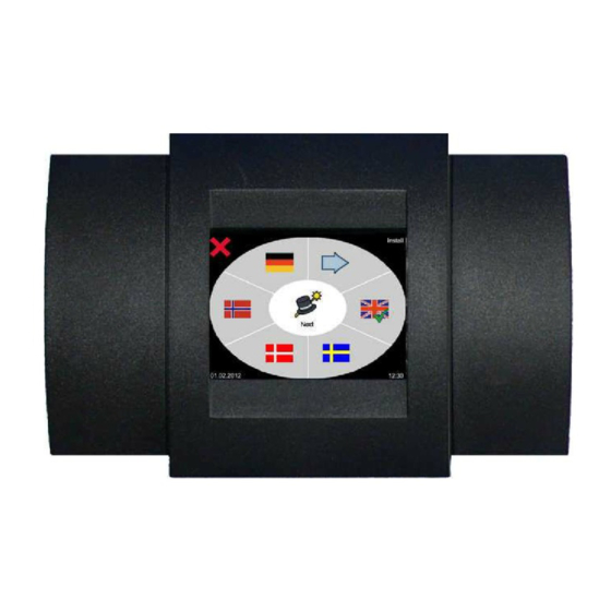
Page 29: General Notes
The language selection is confirmed with a green tick. For the choice of other languages: Button for the next pages (2 + 3) of the current menu. Press to go to the next menu “Communication mode recognition”. © Vestamatic GmbH - 29 - Subject to modifications! -
Page 30: Communication Mode Recognition
The rain sensor and the thermostat are not recognised automatically. If these sensors are installed, each sensor must be activated manually. To do this, touch the appropriate symbol so that the symbol appears over the appropriate sensor. © Vestamatic GmbH - 30 - Subject to modifications! -
Page 31: Selection Of Connected Channel Group
= roller shutter sun, temperature = lighting no sensor assignment possible = ventilation temperature = heating temperature = no function / no sensor assignment possible not connected to this channel group © Vestamatic GmbH - 31 - Subject to modifications! -
Page 32: Lux Sensor Assignment
Art.-no. 01100310 Type WM1 = WS XS Alu, Art.-no. 01100410 Type WM2 = WS Classic M, Art.-no. 01100235 Press for the previous menu. Press to return to the menu “Sensor Select”. © Vestamatic GmbH - 32 - Subject to modifications! -
Page 33: Temperature Sensor Assignment
, the device lock function will be disabled and you will go straight to the “Wizard Finish” menu. Press for the previous menu. … please see also next page. © Vestamatic GmbH - 33 - Subject to modifications! -
Page 34: Wizard End
Risk to life and property due to sudden movement of connected sunshades, mechanisms or skylights! Press to close the wizard. © Vestamatic GmbH - 34 - Subject to modifications! -
Page 35: Information For The User General Notes
To stop the sunshade/skylight while it is moving, simply press the opposite button. Manual control of lighting/heating/ventilation Lighting, heating or ventilation Press to switch on, Button means switched on. Lighting, heating or ventilation Press to switch off, Button means switched off. © Vestamatic GmbH - 35 - Subject to modifications! -
Page 36: Weather Info / Display Lock / Comfort Program
Press button for 3 seconds to lock the display. The symbol will appear, indicating that the display is locked. To unlock the display, press and hold button 3 seconds. Example © Vestamatic GmbH - 36 - Subject to modifications! - Page 37 A retract or skylight close command is always performed before a comfort program is carried out. After this command has been completed the devices will move to the set position for that particular comfort program. © Vestamatic GmbH - 37 - Subject to modifications!
-
Page 38: Basic Settings
Information for the user – Basic settings Quick reference guide © Vestamatic GmbH - 38 - Subject to modifications! -
Page 39: Detail
The clock is internally powered by a buffer battery which means that the date and time are saved even if there is a power failure. If a DCF Receiver is connected and there is sufficient clock signal, the time and date will be set automatically. © Vestamatic GmbH - 39 - Subject to modifications! -
Page 40: Setting The Display Colour Selection
1. NOTE! A fire alarm results in the immediate retraction of sunshades and closure of skylights. Connected ventilators and/or heating units are also switched off immediately. © Vestamatic GmbH - 40 - Subject to modifications! -
Page 41: Network Settings (Without Function)
The logbook may only be deleted by the manufacturer. All entries are stored electronically and will not be lost even in the event of a power failure or if the control box’s battery is removed. © Vestamatic GmbH - 41 - Subject to modifications! -
Page 42: Display Contact Details
Risk to life and property due to sudden movement of connected sunshades, mechanisms or skylights! Press to retract all sunshades to their upper end positions and/or to close the skylight. © Vestamatic GmbH - 42 - Subject to modifications! -
Page 43: Touchscreen Calibration
After you have pressed the button you will be requested to enter a security code. You will not be able to make any changes without entering a security code. © Vestamatic GmbH - 43 - Subject to modifications! -
Page 44: Restore Factory Settings
You will not be able to make any changes without entering a security code. See details of the password input menu on page 29. © Vestamatic GmbH - 44 - Subject to modifications! -
Page 45: Fine Adjustments
Temperature Handheld function transmitter Temperature threshold 1 Programming / Deleting Temperature threshold 2 Runtime for temperature (without function) threshold 2 Reset delay Temperature unit © Vestamatic GmbH - 45 - Subject to modifications! -
Page 46: Sun Function
= rain function = wind function = temperature function = to page 2 of the fine adjustments or back to page 1. Page 1 Press to return to the user menu. © Vestamatic GmbH - 46 - Subject to modifications! -
Page 47: Setting Extension Sun Threshold
The threshold value can be set separately using the buttons. Programmable range: 10 – 99 kLux Press to return to the retract time delay menu. Press for the sun motor runtime menu. © Vestamatic GmbH - 47 - Subject to modifications! -
Page 48: Setting Number Of Sun-Dependent Extension Commands Per Day
This may cause serious personal injury or damage to property! See details of the password input menu on page 29. © Vestamatic GmbH - 48 - Subject to modifications! -
Page 49: Setting Manual Extension When Rain/Frost
If this is required, press the appropriate symbol. The symbol will then appear by Press to return to the rain sensitivity setting menu. Press to go to the detail 1/5. © Vestamatic GmbH - 49 - Subject to modifications! -
Page 50: Wind Function
Programmable range: off, 10 – 99 km/h. Press to return to the wind threshold 1 menu. Press for the wind response delay menu. NOTE! Wind threshold 2 cannot be set higher than wind threshold 1. © Vestamatic GmbH - 50 - Subject to modifications! -
Page 51: Setting Wind Response Delay
To set the wind unit, press the appropriate symbol. The symbol will then appear by the selected unit. Press to return to the wind reset delay menu. Press to go to the detail 1/5. © Vestamatic GmbH - 51 - Subject to modifications! -
Page 52: Temperature Function
Programmable range: off, 15 °C – 34 °C Press to return to the temperature threshold 1 menu. Press for the runtime for temperature threshold 2 menu. © Vestamatic GmbH - 52 - Subject to modifications! -
Page 53: Setting Temperature Reset Delay
(F). To set the temperature unit, press the appropriate symbol. The symbol will then appear by the selected unit. Press to return to the temperature reset delay menu. Press to go to the detail 1/5. © Vestamatic GmbH - 53 - Subject to modifications! -
Page 54: Motor Run Time
(retracts) to enable the slats to be positioned to the correct angle. The tilt function is performed in both automatic and manual operation mode, depending on setting. © Vestamatic GmbH - 54 - Subject to modifications! -
Page 55: Selection Of Tilting Type
During the period of time between time 4 and for the individual seasons” or the “Set tilting time 1, the tilting time from time 4 will continue assignment” menu. until time 1 is activated again. © Vestamatic GmbH - 55 - Subject to modifications! -
Page 56: Setting Tilting Time "Season
2/5 menu. NOTE! If the sun and temperature function is assigned to a channel group, the tilting function will automatically be selected/deselected when triggered by sun and temperature. © Vestamatic GmbH - 56 - Subject to modifications! -
Page 57: Continuous Up Command / Continuous Down Command
By pressing the group button no operation via display is possible. = to page 3 of the fine adjustments or back to page 1. Press to return to the user menu. © Vestamatic GmbH - 57 - Subject to modifications! -
Page 58: Mc Dz M/J Function
2 seconds is enabled. This means that the runtime command is not executed for 2 seconds. Press the symbol to activate the function. Function may only be activated for the following control types = blinds © Vestamatic GmbH - 58 - Subject to modifications! -
Page 59: Holiday Function
Further adjustments can only be made when the Astro function is active ( Press the symbol to activate the Astro function. Press to return to the detail 3/5 menu. Press for the longitude LON menu. © Vestamatic GmbH - 59 - Subject to modifications! -
Page 60: Setting Longitude Lon
+/- 59 minutes with the buttons Press to return to the up time correction menu. Press to go to the detail 4/5. © Vestamatic GmbH - 60 - Subject to modifications! -
Page 61: Detail
(Monday to Sunday) or to return to detail 4/5. Press to go to the next day in the menu (Monday to Sunday) or to return to detail 4/5. © Vestamatic GmbH - 61 - Subject to modifications! -
Page 62: Down Time Function
(Monday to Sunday) or to return to detail 4/5. Press to go to the next day in the menu (Monday to Sunday) or to return to detail 4/5. © Vestamatic GmbH - 62 - Subject to modifications! -
Page 63: Programming/Deleting Handheld Transmitter (Without Function)
The connected heating system can additionally be switched on when the temperature drops below additional threshold as an protection against frost. Function may only be activated for the heating type of control system. © Vestamatic GmbH - 63 - Subject to modifications! -
Page 64: Setting Temperature Threshold
Celsius (°C), kelvin (K) or Fahrenheit (F). To set the temperature unit, press the appropriate symbol. The symbol will then appear by the selected unit. Press to return to the reset delay menu. Press for the detail 5/5 menu. © Vestamatic GmbH - 64 - Subject to modifications! -
Page 65: Ventilation Function
Celsius (°C), kelvin (K) or Fahrenheit (F). To set the temperature unit, press the appropriate symbol. The symbol will then appear by the selected unit. Press to return to the reset delay menu. Press for the detail 5/5 menu. © Vestamatic GmbH - 65 - Subject to modifications! -
Page 66: Control System Warning Signals
If the connection cable for the temperature sensor TS Pro XL is damaged, this fault will be indicated on the display. The display will then change to show the sensor error with details of that sensor. © Vestamatic GmbH - 66 - Subject to modifications! -
Page 67: List Of Cities For The Astro Function
Dublin - 06°14 53°19 Luxemburg 06°08 49°37 Oslo 10°44 59°54 Trondheim 10°25 63°25 Amsterdam 04°53 52°22 Eindhoven 05°28 51°26 Rotterdam 04°28 51°55 Moscow 37°36 55°45 Gothenburg 11°58 57°42 Stockholm 18°03 59°19 © Vestamatic GmbH - 67 - Subject to modifications! -
Page 68: Symbol Description
Control system type: lighting Control system type: Control system type: blind ventilation Control system type: heating Control system type: skylight Not connected, Control system type: shutter not connected to this channel group © Vestamatic GmbH - 68 - Subject to modifications! - Page 69 Sensor assignment: temperature display box temperature sensor sensors TE Indoor or TE Outdoor Rain sensor activation DCF radio-controlled clock receiver RD +1 °C or RD -20 °C Move to safety position © Vestamatic GmbH - 69 - Subject to modifications!
- Page 70 Below set temperature Info on retract clock function Info on extend clock function Info on retract wind function Info on retract maintenance function Info on extend maintenance function Info move to safety position © Vestamatic GmbH - 70 - Subject to modifications!
- Page 71 Manual release following fire alarm Automatic release following fire alarm Network settings Display logbook (without function) Display manufacturer contact Display software version Move to safety position Touchscreen calibration Display/start wizard Restore factory settings © Vestamatic GmbH - 71 - Subject to modifications!
- Page 72 Retract / skylight open time function Extend / skylight close time function Programming/Deleting handheld Automatic mode setting transmitter (without function)) Teach in handheld transmitter Delete handheld transmitter (without function) (without function)) Heating function Ventilation function © Vestamatic GmbH - 72 - Subject to modifications!
-
Page 73: Manufacturer's Default Settings
2. Tilting time “Table” Tilting time January, Time 1 (8.00 a.m.) Tilting time January, Time 2 (11.00 a.m.) Tilting time January, Time 3 (2.00 p.m.) Tilting time January, Time 4 (5.00 p.m.) © Vestamatic GmbH - 73 - Subject to modifications! - Page 74 Down time correction UP time function lighting / ventilation / heating ON 8:00 Monday Duration 8:00 Tuesday Duration 8:00 Wednesday Duration 8:00 Thursday Duration Friday 8:00 Duration Saturday 8:00 Duration Sunday 8:00 Duration © Vestamatic GmbH - 74 - Subject to modifications!
- Page 75 10 min. °C Temperature unit Ventilation function Temperature threshold 23° Reset delay 10 min. Temperature unit °C Fire function with with with with with with Setting confirmation confirmation confirmation confirmation confirmation confirmation © Vestamatic GmbH - 75 - Subject to modifications!
-
Page 76: Personal Settings
Reset delay Temperature unit Motor run time Setting Tilting function Tilting time spring Tilting time summer Tilting time autumn Tilting time winter Tilting assignment in relation to Temperature Manual operation Time © Vestamatic GmbH - 76 - Subject to modifications! - Page 77 / ventilation / heating ON Monday Duration Tuesday Duration Wednesday Duration Thursday Duration Friday Duration Saturday Duration Sunday Duration DOWN time function lighting / ventilation / heating OFF Monday Duration Tuesday Duration © Vestamatic GmbH - 77 - Subject to modifications!
- Page 78 Duration Wednesday Duration Thursday Duration Friday Duration Saturday Duration Sunday Duration Heating function Temperature threshold Anti-freeze Reset delay Temperature unit Ventilation function Temperature threshold Reset delay Temperature unit Fire function Setting © Vestamatic GmbH - 78 - Subject to modifications!
-
Page 79: Troubleshooting
Check the lux sensor position that are too low and change if necessary Lux sensor is soiled or covered (see p. 17) Remove any soiling (see p. 17) © Vestamatic GmbH - 79 - Subject to modifications! - Page 80 (see p. 47) too late Response time setting Decrease sun function is too long response time (see p. 47) © Vestamatic GmbH - 80 - Subject to modifications!
- Page 81 3 seconds in response function (see p. 58) Runtime is set to 3 seconds to sun / temperature Adjust sunshade runtime (see pp. 48, 53 and 54) © Vestamatic GmbH - 81 - Subject to modifications!
-
Page 82: Cleaning / Disposal Of Waste
Information for the user – Customer service Vestamatic GmbH Dohrweg 27 41066 Mönchengladbach / Germany Phone: +49 21 61 / 29 408-0 Fax: +49 21 61 / 29 408-20 info@vestamatic.com www.vestamatic.com © Vestamatic GmbH - 82 - Subject to modifications!
Need help?
Do you have a question about the Touch Centre XL 4C Wired and is the answer not in the manual?
Questions and answers