Table of Contents
Advertisement
Quick Links
Part Number
MAXREFDES132#
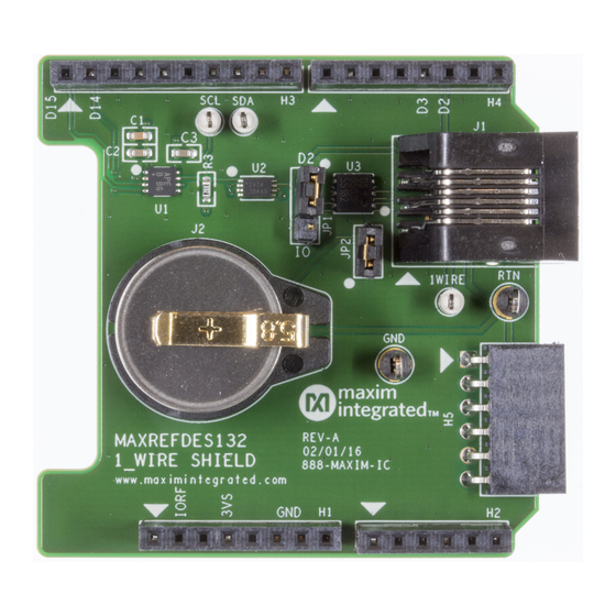
MAXREFDES132# System Board
Overview
MAXREFDES132# provides a convenient platform for interfacing with 1-Wire
Evaluation Kits (EV kits), and iButton
bang master on D2 of the Arduino form-factor pinout.
Description
1-WIRE MASTER, ARDUINO
SHIELD FORM FACTOR
®
devices using the DS2484 I
®
devices, 1-Wire
2
C-to-1-Wire master, or a bit-
Advertisement
Table of Contents

Subscribe to Our Youtube Channel
Related Manuals for Maxim Integrated MAXREFDES132


Summary of Contents for Maxim Integrated MAXREFDES132
- Page 1 1-WIRE MASTER, ARDUINO MAXREFDES132# SHIELD FORM FACTOR MAXREFDES132# System Board Overview ® MAXREFDES132# provides a convenient platform for interfacing with 1-Wire devices, 1-Wire ® Evaluation Kits (EV kits), and iButton devices using the DS2484 I C-to-1-Wire master, or a bit-...
- Page 2 Maxim’s 1-Wire bus continues to flourish in the era of IoT. This unique protocol provides communication and power along a single wire, at relatively long distances. Now, with MAXREFDES132#, Maxim merges a reliable, hardware based 1-Wire master with Arduino and mbed.org platforms.
- Page 3 The DS2484 I C-to-1-Wire master provides internal user-adjustable timers that relieve the system host processor from generating time-critical 1-Wire waveforms, supporting both standard and overdrive 1-Wire communication speeds. In addition, the 1-Wire bus can be powered down under software control through D3 of the Arduino form-factor pinout. D2 can be used to bit bang the 1-Wire bus by installing JP1 on pins 1-2 and installing JP2 to connect the provided pullup to the bus.
- Page 4 Figure 2. Demo program flow chart.
- Page 5 2. Connect MAXREFDES132# to your Arduino board. 3. Ensure JP1 and JP2 are configured properly for the 1-Wire master you would like to use 1. DS2484 – JP1 on pins 2-3, JP2 removed...
- Page 6 2. Bit-Bang master – JP1 on pins 1-2, JP2 installed. 4. Install the provided DS1920 iButton, or user supplied 1-Wire device 5. Connect USB cable from the PC to your Arduino board. 6. Ensure that you have the COM port that your Arduino board is connected to selected in the Arduino IDE.
Need help?
Do you have a question about the MAXREFDES132 and is the answer not in the manual?
Questions and answers