Table of Contents
Advertisement
Quick Links
Advertisement
Table of Contents

Summary of Contents for Manley MicMAID
-
Page 2: Table Of Contents
CONTENTS INTRODUCTION............................3 MAINS CONNECTIONS........................4 THE FRONT PANEL..........................5 THE BACK PANEL..........................6 THE ROUTING MATRIX........................7 THE MONITOR SECTION........................7-8 VARIABLE PHASE..........................9 THE FADER.............................9 THE PICKLE REMOTE..........................9 TROUBLESHOOTING..........................10 BLOCK DIAGRAM..........................11 SPECIFICATIONS..........................12 rev 6.78.12 TS... -
Page 3: Introduction
INTRODUCTION THANK YOU!..for purchasing the Manley MicMAID. This unit was designed to ll a particular niche in the business that has never really been addressed: auditioning and selecting microphones and microphone pream- pli ers. Proper pairing of mics and preamps has always been (and always will be!) a vital step in the tracking process, but there has never been a simple, accurate way of doing this. -
Page 4: Mains Connections
Note: This unit has been factory wired for your country. If you plan to take the unit to countries with a differ- ent mains voltage you will need to send the MicMAID to a quali ed service technician, or contact the Manley Labs Service Center (email: service@manleylabs.com) for the correct transformer primaries wiring conver-... -
Page 5: The Front Panel
In general, if there is an amp involved then the best place to start is in the ““LIFT”” position. FADER: 1/4”” TRS jack for inserting a fader to control the MicMAID’’s MON/REC output level. (For more information, see page 9). -
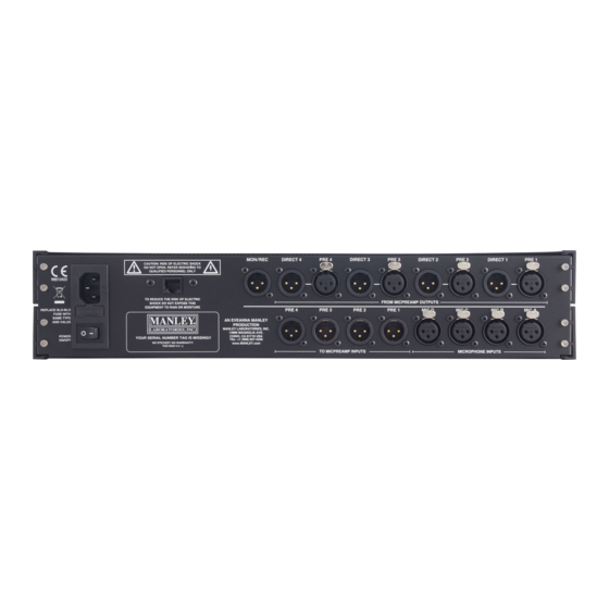
Page 6: The Back Panel
Section. The GAIN TRIM knob and the VARIABLE PHASE section of the front panel are only usable via this output. All other outputs are passive. For more on the Monitor section, continue on to the next page. G. RJ-45 Connector: Used to connect the MicMAID ““pickle”” remote. See page 9 for details. -
Page 7: The Routing Matrix
- let’’s use PRE 1. Now, MIC A is hardwired to the input of PRE 1, and the output of PRE 1 is hardwired to the DIRECT 1 output on the back of the MicMAID - you can treat that output as the output of the mic preamp, as it simply mirrors it. -
Page 8: The Monitor Section
***NOTE: When power is turned on, Snapshot 1 is automatically loaded. This makes it easy to return to a favorite setup. To make MicMAID power up with ‘‘factory default’’ settings, load Snapshot 0, then save it as Snapshot 1. *** ***ANOTHER NOTE: When the unit is powered down, snapshots remain saved, as does the Brightness set- ting. -
Page 9: Variable Phase
This helps you keep track of the Monitor Section’’s signal path even if you are unable to see the MicMAID itself from wherever you are sitting, standing, lying down, so on and so forth. -
Page 10: Troubleshooting
Does one or more of your microphones need phantom power? If the microphone needs it and the MicMAID is not providing it, there will be little or no audible signal. See page 5 for details on how to turn on the phantom power for each microphone. Remember - in the interest of your microphones’’... -
Page 11: Block Diagram
BLOCK DIAGRAM... -
Page 12: Specifications
SPECIFICATIONS Operation Voltage......100/120/220/240VAC, 50 –– 60 Hz (main input voltage selectable internally via rewiring) Current Draw........Line in voltage 120VAC Idle: 0.1 Amps / 12W; Max: 0.17 Amps / 20W Mains Fuse.........Type: 5x20 mm glass body SLO-BLO 500mA (100/120VAC) 250mA (220/240VAC) Instrument Input.........Input Impedance: 120K Ohms Gain Ratio: 12:1 Step down.
Need help?
Do you have a question about the MicMAID and is the answer not in the manual?
Questions and answers