Table of Contents
Advertisement
Quick Links
Advertisement
Table of Contents

Subscribe to Our Youtube Channel
Related Manuals for SHERCO ST Series


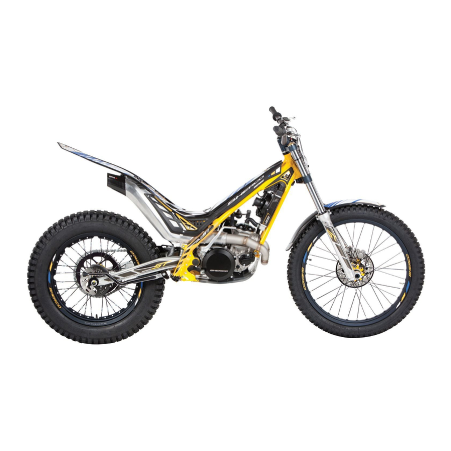
Summary of Contents for SHERCO ST Series
- Page 1 ST SERIES...
-
Page 3: Table Of Contents
❱❘ Ignition assembly ........... 32 ....Erreur ! Signet non défini. FOREWORD ❱❘ Selection mechanism ..........33 ST SERIES TOOLS LIST .. Erreur ! Signet non défini. ❱❘ Kicker shaft mounting ..........34 ❱❘ Primary transmission and clutch ......34 TECHNICAL SHEETS .. -
Page 4: Foreword
This manual is primarily intended for qualified mechanics working in a properly equipped workshop. The execution of the various operations requires solid mechanical knowledge and SHERCO tools specific FOR the 125/250/300 ST engines. This workshop manual complements the user manual for SHERCO 125/250 and 300 ST. ST SERIES... - Page 5 ST SERIES TOOLING LISTING Tools References Designation R172 Clutch lock Water pump bearing tool 2080 2074 Starter shaft seal tool Water pump tip tool R232 Barrel bearing tool R465 Spring block (selection finger) 2073 Engine support 1821 Magnetic flywheel puller...
-
Page 6: Engine
5 gears 13 : 33 15 : 35 18 : 33 24 : 26 31 : 20 Final transmission 9 X 42 9 X 44 9 X 44 Clutch Diaphragm system, hydraulic control Starter Retractable gear and kick system ST SERIES... -
Page 7: Cycle Parts
Aluminium swing arm Forward / reverse stroke FACTORY 165/175mm RACING 165/175mm Front brake Disc Ø 185mm Rear brake Disc Ø 145mm Front tire 2,75-21’’ Rear tire 4,00-18’’ Tire pressure 0.4/0.3 bar Capacity 2,4L Fuel capacity 1322mm Wheelbase Weight 68 kg ST SERIES... -
Page 8: Original Settings Carburetor
0.5 T0 1 0.5 T0 1 Idle jet 2 000 m Needle Needle position 1 000 m Main jet Air screw 0.5 T0 1 0.5 T0 1 0.5 T0 1 Idle jet Needle Needle position 1000 m Main jet ST SERIES... -
Page 9: Front Fork
Right arm oil level 75 mm REAR SHOCK Settings Factory – shock REIGER 65 N/mm Spring Preload spring 7.0mm +/- 0.8mm Restrictor 1.55 mm Rebound 32 clicks open 50 clicks max. Setting Racing – Shock OLLE Spring 6.2kg/mm ST SERIES... -
Page 10: Cycle Parts
1.2 Front disc replacement • When replacing the front brake disc, apply when reassembling the Loctite 243 and on the screws and tighten to a torque of 12Nm • Proceed in the reverse process and lightly grease the front axle. ST SERIES... -
Page 11: Fork Disassembly
When reassembling, install the steering column lock nut and tighten it so that that the fork turns • freely and without hard point. Then place the top triple clamp and tighten the upper steering column nut to 20 Nm. ST SERIES... -
Page 12: Fork Maintenance
• Hold the rod inside the axle [3] then empty the oil in a container by moving back and forth as shown in the photo. Place the suspension arm vertically and pour 250cc of new oil inside. • WARNING Use oil type SAE 5. ST SERIES... - Page 13 • Tighten the plug [4] with the nut [5] to a torque of 12Nm • Tighten the plug on the tube to a torque of 12Nm 1.4.2 Oil change on the left side • Unscrew the cap [6] using a 17mm wrench. • Remove the tapered spacer ST SERIES...
- Page 14 Oil level : 130mm Reassemble in order, the spring, the washer, the spacer, the conical spacer then the top cap • • Place the fork in a vice using a protection for the tube and tighten the plug to 12N m. ST SERIES...
-
Page 15: Rear
• When replacing the rear brake disc, apply when reassembling the Loctite 243 and on the screws and tighten to a torque of 12 Nm.. • Reassemble the assembly following the reverse process and lightly greasing the rear wheel axle. ST SERIES... -
Page 16: Swingarm Bearing Control
• Check the needle cages on each side of the arm. In case of corrosion, replace them with new references C151, otherwise grease them before reassembly • Reassemble the assembly following the reverse process and lightly greasing the swingarm and connecting rod pins. ST SERIES... -
Page 17: Control Of Links
• Remove the spacers from the links and check the friction rings [4]. If there is any wear, replace them with new ones. • Reassemble the assembly by following the reverse process and taking care to grease all the axes and bearings. ST SERIES... -
Page 18: Operations Requiring Removal Or Not Of The Engine
• Crankshaft (including connecting rod kit) • Complete gearbox Crankshaft bearing • • Gearbox bearing • Piston Cylinder • Head cylinder • • Ignition • Kick starter clutch • Water pump • • Gearbox selection ST SERIES... -
Page 19: Engine Removal / Assembly
For reassembly proceed in the reverse direction to disassembly respecting the tightening torques of the screws and nuts Tightening torque: Engine axles : 40Nm Swingarm nut : 50 Nm Slave cylinder screws: 10 Nm Head cylinder holder screws : 23Nm Exhaust screws: 10Nm ST SERIES... -
Page 20: Disassembly Of The Engine
[2], allow the oil to drain by tilting the motorcycle. ❱❘ Removal of front sprocket and selector • Remove the pin [3] [4]. • Remove the front sprocket • Remove the screw and take out the selector. • Remove the clutch push rod. ST SERIES... -
Page 21: Removing The Cylinder Head, Cylinder And Piston
DISASSEMBLY OF THE ENGINE ❱❘ Removing the cylinder head, cylinder and piston Remove the M6 screws • remove the cylinder head and the O- rings. [2]. Remove the 4 cylinder nuts • • Remove the cylinder. • Hide the housing. ST SERIES... -
Page 22: Removing The Clutch Cover
Remove the base gasket. • ❱❘ Removing the clutch cover Remove the screws and the water pump • cover. Remove the seal. Remove the screws and remove the • clutch cover. Remove the gasket. • ST SERIES... -
Page 23: Clutch And Primary Gear Removal
R172. ❱❘ Kick axle removal • Remove the clip then remove the idler gear Remove the M6 screw and the retaining plate • Take out the kick axle paying attention to the spring. • ST SERIES... -
Page 24: Removal Of The Selection
Loosen the M6 screw then take out • the selection finger. Loosen the M6 screw [2] then remove • the selection star. WARNING Be careful not to lose the needle on the back of the selection star ST SERIES... -
Page 25: Removing The Ignition
Remove the previously loosened nut • [1]. Fit the extractor reference R075 and • [3]. tear off the magnetic flywheel ❱❘ Intake pipe and reed box • Remove the 4 screws M5 • Remove the intake pipe, reed box and gaskets. ST SERIES... -
Page 26: Removal Stator
Tilt the engine so that the ignition side is facing • you. Remove the 10 fixing screws. • Raise the left crankcase with small plastic • hammer on the gearbox output shaft to separate from the other half. ST SERIES... -
Page 27: Removing The Gear Box
• Take out the left fork and the central fork. • Remove all of their bearings, the primary, secondary shaft, barrel and right fork simultaneously. WARNING When removing, take care to identify the location of the washers at the end of the shaft. ST SERIES... -
Page 28: Removing The Connecting Rod Assembly
Clean all the parts and check if they are worn, replace them if necessary. • WARNING When the engine is completely dismantled, it is preferable to replace all gaskets, oil seals, O-rings as well as the bearings. ST SERIES... -
Page 29: Engine Element Control
V-shaped shims, and place a comparator as shown in the image in position [A]. • Then slowly turn the crankshaft. The maximum difference between the measurements corresponds to the offset of the crankshaft. Crankshaft Offset: Standard: 0.03 mm Limit: 0.05 mm ST SERIES... -
Page 30: Piston
Standard : 17,998 mm Limit: 14,995 mm Limit : 17,995mm Piston pin hole diameter for 125cc : Piston pin hole diameter for 250/300cc : Standard : 15,003mm Standard : 18.002 mm Limit : 15,007mm Limit : 18.006 mm ST SERIES... -
Page 31: Piston / Cylinder Condition Check
❱❘ Reed box, inlet pipe Over time the carbon reeds gradually lose • their elasticity, which causes a loss of power. Replace the worn or damaged reed. • Check the condition of the intake pipe, • especially if it is not cracked. ST SERIES... -
Page 32: Clutch
WARNING When disassembling the discs, hold them with a plastic collar so as to maintain their position and order of assembly. Worn discs which are not reassembled strictly in the same way can cause vibrations in the clutch. ST SERIES... -
Page 33: Gearbox
Make sure that the shafts shims are in place. Slightly pull out the secondary shaft and hold • the 4th gear up so that the fork is in place in the barrel track. Then insert the assembly into the crankcase bearings. ST SERIES... -
Page 34: Reassembling The Engine
❱❘ Ignition assembly Mount the stator on the crankcase and make sure • that the marks are aligned. Tighten the 3 M6 screws to 10 Nm. • Position the hall sensor and tighten the two screws to 8 Nm. ST SERIES... -
Page 35: Selection Mechanism
Check if the springs of the return spring are • against the finger in the crankcase on each side. Fit the selector and shift all gears. (rotate the • gearbox shafts to facilitate shifting). Remove the selector again. • ST SERIES... -
Page 36: Kicker Shaft Mounting
Thread the gear, the washer and the nut on the • crankshaft tail. Thread the washer onto the primary shaft • [2], Place the idler gear making sure to put the • lower and upper washers in place and then hold it with its circlip. ST SERIES... - Page 37 1 The push rod of the clutch rod with the actuating cup. 2 Metal and friction discs (in the same order as when disassembled). 3 Levers (chamfer up) 4 Pressure plate 5 Preload washer 6 Spring 7 Spring cup Tighten the Torx screws to 7Nm. • ST SERIES...
-
Page 38: Clutch Cover
Place the seal on the water pump cover and • stick it with a light layer of grease. Position the 4 M6 screws and tighten to 10 Nm. • WARNING Always replace the cooling bleed screw seal with a new reference M277 ST SERIES... -
Page 39: Piston / Cylinder
Clean the cylinder and cylinder head gasket surfaces. • Fit the O-rings (glue them with grease if necessary) • Fit the head. • Put new copper washers ref 2390 (Factory only) • Fit the screws M6 • Tighten crosswise to 10 Nm. • ST SERIES... -
Page 40: Reed Box, Inlet Pipe
Mount the intake pipe with the 4 M5 screws, • tighten them to 6Nm. ❱❘ Front sprocket Fit the retaining circlip on the engine side. • Fit the front sprocket, number of teeth • outwards. Fit the retaining ring on the outside. • ST SERIES... -
Page 41: Tightening Torques Table
0,6 N·m Screws M-6 12 N·m Screws M-8 24 N·m Screws M-10 40 N·m Rear wheel axle nut 100 N·m Front wheel axle 100 N·m Lower steering nut 20 N·m Upper steering nut 20 N·m Swing arm 50 N·m ST SERIES... -
Page 42: Electrical Part
ELECTRICAL PART ❱❘ Electrical components Position Designation Ventilator T° Sensor Ignition coil Regulator Ignition ST SERIES... -
Page 43: Ignition Stator Control
Wire black – white Ω +/- 20%% Wire brown – white ❱❘ Voltage Regulator Voltage regulator: • On regulator output (Caliber 20V continuous) At 3500 RPM: 14.4V +/- 0.5V Maximum output current : 15 A Max operating temperature : 110°C ST SERIES... -
Page 44: Cdi
CDI. Secondary coil: measure the resistance • between the ground and the output to the spark plug. Primary resistance : O.25 KΩ +/- 15% à • 20°C Secondary resistance: 4.78 KΩ +/- 20% à • 20°C ST SERIES... -
Page 45: Temperature Sensor
1081 ❱❘ Ventilator Disconnect the fan from the harness. • Connect a 12V battery directly to the fan as • shown in the diagram. Check that the fan rotates correctly without • any hard point or abnormal noise. ST SERIES... -
Page 46: Electric Drawing
CABLE SCHEMATICS ❱❘ Homologated light harness ST SERIES... - Page 47 CABLE SCHEMATICS ❱❘ Homologated light harness ST SERIES...
-
Page 48: Racing Light Harness
CABLE SCHEMATICS ❱❘ Racing light harness ST SERIES... -
Page 49: Principal Harness
CABLE SCHEMATICS ❱❘ Principal harness ST SERIES... - Page 50 CABLE SCHEMATICS ❱❘ Principal harness ST SERIES...
Need help?
Do you have a question about the ST Series and is the answer not in the manual?
Questions and answers