Table of Contents
Advertisement
Quick Links
Advertisement
Table of Contents

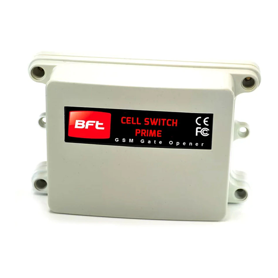
Summary of Contents for BFT Cell Box Switch
- Page 1 Installation & User Manual For Cell Box Switch GSM Cellular Gate opener and GSM alarm signalling device. BFT Americas 6100 Broken Sound Parkway N.W. Suite 14, Boca Raton, FL 33487 www.bft-usa.com Toll Free: 877-995-8155 Office: 561-995-8155 Fax: 561-995-8160 P a g e...
-
Page 2: Table Of Contents
Contents …………….Pg 3 Overview of system …………….Pg 3 Site Survey …………….Pg 3 SIM card …………….Pg 3 Power …………….Pg 4 Inserting the SIM card …………….Pg 4 Connections on the GSM Controller …………….Pg 4 Output Connections example …………….Pg 5 Notification Feature …………….Pg 5 Powering Up …………….Pg 6 Programming... -
Page 3: Overview Of System
Overview of System Please read this entire manual before attempting to install this system. This system should only be installed by a professional automatic gate installer or access control specialist dealer. It is recommended that the system be set up, configured, commissioned and tested on a workshop bench before taken to site for installation. -
Page 4: Inserting The Sim Card
Inserting the SIM card Note: This unit is a dual 2G/3G quad band system, operating on standard 2G network frequencies of 850/900/1800/1900MHz and 3G frequencies of 900/2100MHz. close Do not use a SIM card for a tablet, as these only support data, and do not support voice and SMS. -
Page 5: Notification Feature
Alternative Keypad Wiring for Notification Feature The Cell Box Switch has an additional feature which sends an SMS to a master user when the GSM unit triggers it’s outputs. So if the user wants to know when an external device such as a keypad is triggered, then wire a keypad output to egress input of the GSM as shown…... -
Page 6: Programming
Programming TIP: The GSM unit programming is by sending SMS text messages to the unit from a phone. Check Reception Send the SMS *20# as shown, to the SIM card number of the intercom. The unit should reply with a *20# reception level between 1 and 31. -
Page 7: Programming As An Alarm Device
Programming as an Alarm Dialling Device This advanced GSM unit is also able to be used as a GSM alarm device. If the input terminals are triggered with a closing connection, the device will call up to 4 phone numbers in sequence. 9999#111telephonenumber# Tip: Up to 4 telephone numbers can be dialled in the event of an alarm. -
Page 8: Controlling Relays As An Alarm Dialler
Scheduled service calls Store a service number to receive a scheduled call or SMS from 77number# the unit. Useful for SIM cards which are not often used to prevent switch off by the network provider. Set the time schedule for the intercom to make a scheduled call 57??# or SMS to the service number. -
Page 9: Control By Sms
Android and iPhone users can download an optional app called Cell Box PLUS. This app performs 3 main functions.. Speed dials your Cell Box Switch when the trigger button is pressed. Sends pre-configured SMS messages to latch and unlatch relays. -
Page 10: Iphone App Setup
Once the buttons and screen labels are entered and saved, then the app should be ready to use. Main Trigger button Un-Latch Relay Button Use this to speed dial the Sends a pre-configured Switch and momentary SMS to unlatch the relay trigger relay 1. -
Page 11: Troubleshooting Guide
Troubleshooting guide Q. The unit will not power up. No LEDs on. A. Check alarm or CAT5 cable has not been used to power the device. If it has, the warranty will be void. Please remove and replace as per instructions. Q. -
Page 12: Change History
Change History Key: H = Hardware PCB version S = Software version Reason for change First version. Power chip upgraded to work on 24v dc (24v adaptor in kits). Software feature added for call log to show last 25 caller ID calls. Main capacitor, regulator &...


Need help?
Do you have a question about the Cell Box Switch and is the answer not in the manual?
Questions and answers