Table of Contents
Advertisement
Quick Links
Advertisement
Table of Contents

Subscribe to Our Youtube Channel
Related Manuals for EMUS G1

Summary of Contents for EMUS G1
-
Page 1: G1 Battery Management System
G1 Battery Management System User Manual... -
Page 2: Table Of Contents
Table of contents G1 Battery Management System ....................................1 Table of Contents G1 Battery Management System ....................................1 Preface ............................................8 Introduction ........................................... 12 Basics ............................................13 System structure overview ................................13 3.1.1. Control Unit ....................................13 3.1.2. Cell Modules....................................17 3.1.3. - Page 3 Charger ........................................60 4.1.3. CAN-based chargers ................................60 4.1.4. Non-CAN chargers ..................................61 4.1.5. Analog signal controlled chargers ............................62 Cooling fan ......................................62 Heater ........................................63 Indicators ........................................ 63 Insulation fault detector ..................................64 Optimised Battery Charging Level ..............................65 Configuration ........................................
- Page 4 7.1.6. Other specifications` ................................94 Cell Communication Adapters ..............................94 7.1.7. Mechanical specification ................................. 94 7.1.8. Electrical characteristics ................................. 97 7.1.9. Other specifications ...................................98 Current Sensor....................................99 7.1.10. Mechanical specification ..............................99 7.1.11. Electrical characteristics ............................... 102 7.1.12. Other specifications ................................102 Smartphone Connectivity Module .............................
- Page 5 3.2.11. Vehicle speed measurement ............................43 3.2.12. Communication with external devices ........................... 45 3.2.13. Indication ....................................45 Installation ..........................................47 4.1. Control Unit .......................................47 4.1.1. Choosing the power supply strategy ............................47 4.2. Cell Modules ..................................... 50 4.3. Current Sensor....................................52 4.4.
- Page 6 6.4. Setting up password ..................................84 6.5. Exporting and importing configuration ............................ 85 6.6. Control Unit firmware update ..............................86 6.7. CAN Cell Group Module firmware update ..........................86 6.8. Display Unit firmware update............................... 87 6.9. Exporting and importing statistics ............................. 87 6.10.
- Page 7 Release notes: Revision Date Revision Author Changes 2018-11-11 1.2.1 Fixed some mistakes and inaccuracies in chapters 3.2.13.1, 3.2.13.2, 3.2.13.3, 4.13, and 4.14. 2018-12-07 1.3.0 Updated company name and links. Updated information about new and obsolete products. 2019-08-11 1.4.0 Martyna Manual information updated. Chapters 5.2, 5.13 added. Dulevičiūtė...
-
Page 8: Preface
Figure 3.22 Charging indicator timing Figure 3.23 Sound indicator timing Figure 3.24 Low battery indicator timing Figure 4.1 Correct installation of Control Unit and distribution of power supply to other EMUS G1 BMS components Figure 4.2 Power supply strategy 1 Figure 4.3 Power supply strategy 2... - Page 9 Figure 4.16 EMUS G1 Display Unit wiring Figure 4.17 Connecting contactor to EMUS G1 Control Unit: (a) directly, when the rated current of the contactor coil is less than 0.5A; (b) through a relay, when the rated current of the contactor coil is 0.5A or more.
- Page 10 Figure 7.11 EMUS G1 Centralized CAN Group Module (CCGM020A) mechanical drawing and connector’s pinout. All dimensions in millimeters Figure 7.12 EMUS G1 Bus Bar Type Dual Range Current Sensor (CS010B) mechanical drawing. All dimensions in millimeters. Figure 7.13 EMUS G1 Closed Loop Type Dual Range Current Sensor (CS020A) mechanical drawing and connectors pinout.
- Page 11 Table 7.22 EMUS G1 Centralized CAN Group Module (CCGM020A) other specifications Table 7.23 EMUS G1 Bus Bar Type Dual Range Current Sensor (CS010C) wire assignment Table 7.24 EMUS G1 Closed Loop Type Dual Range Current Sensor (CS020A) connector pin assignment Table 7.25 EMUS G1 Dual Range Current Sensor electrical characteristics Table 7.26 EMUS G1 Dual Range Current Sensor other specifications...
-
Page 12: Introduction
This document covers all aspects of using the EMUS G1 BMS, and aims to provide the user with an in-depth knowledge about its core functionality and utility functions, as well as with... -
Page 13: Basics
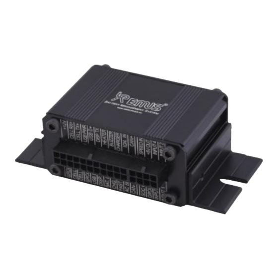
Basics EMUS G1 BMS is a digital, distributed topology battery management system that consists of a main controller, several cell controller boards (one for each individual cell), cell communication adapters, a current sensor, and few other optional components that all serve different purposes. - Page 14 Figure 0.1 EMUS G1 Control Unit Depending on their purpose, all Control Unit pins can be divided into two categories: fixed and remappable. Fixed pins that dedicated for digital communication interfaces and power supply, and their position on the connector is permanent. Remappable pins are quite the opposite –...
- Page 15 BMS activity monitoring – either directly by a third-party controller, or by using the optional first-party EMUS G1 BMS components that are dedicated for this purpose. The RS232 interface is populated as the “DISP. RX”, “DISP.TX” and “GROUND” pins on the main 22 pin connector of the Control Unit.
- Page 16 for driving relays, indicators, etc., or transmitting logic signals to various third-party devices. Likewise, pins that fall into the general-purpose input category are populated on the same connector as the following: • FAST CHG.; • AC SENCE; • IGN.IN. They are used by the Control Unit to read various logic signals from third-party devices. As mentioned already at the beginning of this subsection, general purpose inputs and outputs are remappable, and are named after their default function.
-
Page 17: Cell Modules
Communication Adapters: Top and Bottom Isolators, and CAN Cell Group Modules. 1.1.5.1 Top and Bottom Isolators EMUS G1 Top and Bottom Isolators are a specially designed pair of optical isolators that allow direct serial communication between the Control Unit and the Cell Modules. - Page 18 Modules into several small daisy chains instead of one long chain. This not only eliminates the drawbacks of the Top and Bottom Isolators, but also makes the EMUS G1 BMS callable to serve a virtually unlimited number of cells. Furthermore, it enables the EMUS G1 BMS to manage...
-
Page 19: Current Sensor
16 lithium cells which enables Emus battery management system to save space by reducing the need of having cell modules as each CCGM directly monitors each battery cell. Up to 32 Centralized CAN Cell Group can be connected to the G1 system. -
Page 20: Smartphone Connectivity Module
Figure 0.7 EMUS G1 Dual Range Current Sensor: Bus Bar type 1.1.6.2 Closed Loop Type The second generation, or the Closed Loop type of EMUS G1 Dual Range Current Sensor has an improved design that makes it more rugged, accurate, and less sensitive to the environment factors when compared to the Bus Bar type. -
Page 21: Can Splitter
In the following Figure 0.11 an example of Master/Slave system is presented. This system consists of 2 EMUS G1 Battery Management Systems. Each EMUS G1 Control Unit is responsible for monitoring its battery pack using CAN Cell Group Modules and Cell Modules over Internal CAN Bus.,... - Page 22 • 1x Internal CAN BUS • 2x Common CAN BUS Each EMUS G1 Control Unit must be connected to a different CAN Splitter over „Internal CAN BUS“ terminal. „Common CAN BUS“ terminals are used to interconnect other EMUS G1 CAN...
-
Page 23: Software
1.1.10.2 Control Panel EMUS G1 Control Panel (or simply Control Panel) is the official Windows PC software tool for configuration, maintenance, and diagnostics of the EMUS G1 BMS. It comprehensively displays all BMS activity data received from the Control Unit, gives quick and effortless access to each individual configuration parameter, and allows to easily and safely perform virtually all maintenance operations. - Page 24 uses the measured values to regulate the balancing current in an attempt to keep the cell’s voltage lower than the balancing threshold, while at the same time keeping its own temperature lower than a certain maximum value to protect itself from overheating. The Control Unit retrieves the measured voltage and temperature values, as well as the balancing rate value (which is the duty cycle of the PWM signal that is used for controlling the balancing current) from the Cell Modules by means of request-response"...
- Page 25 Where “Total Number of cells" is the value of a corresponding configuration parameter”. All core EMUS G1 Control Unit functions only use the minimum, maximum, or average values rather than individual cell data, therefore only these aggregated values are normally stored during the periodic cell monitoring process.
- Page 26 2 temperatures: internal – balancing temperature, external – cell temperature. Therefore, Control Panel displays a pair of these temperatures for each battery cell. EMUS CCGM uses a new centralized system where it does not guarantee dedicated temperature sensors for each of battery cells and has only 7 external temperature sensors.
-
Page 27: Current Measurement
The measurement of the battery current in EMUS G1 BMS comprises of two continuous, simultaneously executed processes. During the first process, the Control Unit continuously measures the analog signals given by EMUS G1 Current Sensor using a high sample rate analog- to-digital converter peripheral, and periodically stores averaged measurement results for further processing. -
Page 28: Charging Process And Charging Device Control
EMUS G1 BMS. Various third- party charging devices are supported for that purpose, which can be categorized into three distinct types based on how they are controlled: 1. - Page 29 • Enerwit; • Victron Inverter. Up to 16 identical CAN chargers connected in parallel can be controlled by EMUS G1 BMS if each individual charger is set up to use a unique CAN identifier. The Control Unit detects each charger automatically and relies on the "Number of Chargers" parameter in order to correctly distribute the charging current among all connected chargers.
- Page 30 It is important to note that due to Control Unit’s internal memory limitations EMUS G1 Control Unit can support only one charging device type or model at a time, and it is necessary to re- upload the Control Unit with a different firmware in case it is desired to change the supported type or model.
- Page 31 • When using a non-CAN charging device, the "Pre-Charging stage" is skipped because EMUS G1 Control Unit does not have the ability to effectively reduce its output current without potentially forcing it to function outside of its normal operating conditions.
- Page 32 When using a non-CAN charging device EMUS G1 Control Unit does not have any means to regulate the charging current, therefore in such case this stage is a bit different. When it begins, the charging device is kept on until the maximum cell voltage starts to exceed the "Fully Charged...
- Page 33 "Cell Comm Restore" feature is enabled, EMUS G1 Control Unit will not register a charging error for as long as the "Restore Duration" parameter value. During this time, EMUS G1 Control Unit will go into "Pre-Charging stage"...
- Page 34 The charging process is over when the Control Unit acknowledges that the charging device has been disconnected regardless in which charging stage EMUS G1 Control Unit is at the time and is not resumed but started over if the charging device is reconnected.
-
Page 35: Battery Protections
1.2.5 Battery protections During discharge, EMUS G1 BMS Control Unit protects the battery from operation beyond certain limits of its parameters (voltage, temperature, current) by deactivating the general- purpose output pin mapped with "PF12 Battery Contactor Output"... - Page 36 1.2.5.1 Contactor pre-charge In a lot of different applications, the battery that is managed by EMUS G1 Control Unit connects to a load that has a substantial input capacitance. In such case, it is often desirable to limit the high in-rush current that occurs when the main contactor is closed in order to reduce stress to the internal components of the load device and prevent the contactor from welding.
-
Page 37: Power Reductions
1.2.5.2 External contactor deactivation In case it is desired to allow an external system that utilizes EMUS G1 Control Unit to override the control of the main contactor without compromising the contactor pre-charge functionality, the External Contactor Deactivation feature can be used. When it is enabled, the general- purpose output pin mapped with "PF12 Battery Contactor Output"... -
Page 38: Heater And Cooling Fan Control
In order to allow safe and reliable use of lithium batteries in various climate conditions, EMUS G1 Control Unit offers several different options to control a heater and/or a cooling device. Any of the Control Unit’s general-purpose output pins mapped with the "PF13 Battery Fan Output"... -
Page 39: Dc/Dc Converter Control
BMS remains powered and can potentially drain the battery if it is not charged during that time. EMUS G1 Control Unit has a special feature that allows to disconnect the DC/DC converter automatically in order to prevent such situations. - Page 40 ID of the cell module with minimum temperature, and timestamp of when these values were recorded. The number of times EMUS G1 Control Unit has been powered up. BMS start count Additionally, contains the timestamp of the last occurrence.
- Page 41 The number of times Low Cell Voltage reduction has been activated. Low voltage power reduction count Additionally, contains the timestamp of the last occurrence. The number of times High Discharge Current reduction has been activated. High current power reduction count Additionally, contains the timestamp of the last occurrence.
-
Page 42: Events
• All other statistics are stored directly in EEPROM memory. 1.2.10 Events During operation, EMUS G1 Control Unit keeps a log of the most recent events in its internal non-volatile memory. It consists of 32 entries, each of which stores an event type identifier and occurrence timestamp. -
Page 43: Vehicle Speed Measurement
Control Unit through one of its digital interfaces and monitored in real time on EMUS G1 Display Unit or a third party display, which eliminates the need for a separate electronics for these functions and allows to simplify the electrical system of the vehicle. - Page 44 • Momentary Consumption; • Average Consumption; • Last Trip Average Consumption; Momentary Consumption is updated every 10 milliseconds by using the formula ( 5 ) �� ∙�� ������������������ �������� ������������������ ���������������������� = ( 5 ) �� ������������������ Where �� is the momentary current value, �� is the momentary battery pack voltage ������������������...
-
Page 45: Communication With External Devices
1.2.11.2 Remaining distance estimation EMUS G1 Control Unit estimates the remaining distance based on the calculated values of energy consumption per distance unit, and by assuming that the ratio between the energy remaining in the battery and energy already used in during the current trip is equal to the ratio between the remaining SOC and SOC used since the start of the trip. - Page 46 Charger blinks disconnected 1 blink Pre-heating stage 2 blinks Pre-charging 3 blinks stage 4 blinks Main charging slow stage blink Balancing stage rapid Charging stage blink Charging error Figure 0.21 Charging indicator timing 1.2.13.2 Buzzer A self-oscillating buzzer connected to any general-purpose pin mapped with "PF7 Sound Buzzer Output"...
-
Page 47: Installation
1.3 Control Unit EMUS G1 Control Unit should be tightly secured to a surface using screws, as shown in Figure 0.1. It is recommended to install it small distance away from the battery (ideally in the same enclosure) in order to make the wiring process easy and to keep the wires between different EMUS G1 BMS components short. - Page 48 Control Unit and the rest of EMUS G1 BMS components from the grid using an appropriate isolated AC adapter, as shown in the example in Figure 0.2;...
- Page 49 "PF24 DC/DC Control Output" function. This ensures that EMUS G1 Control Unit does not drain the auxiliary nor the main battery when the system is not in operation, and also protects the main battery from damage due to depletion in case the operator forgets to turn off the ignition key and leaves the system to idle for an ex- tended period of time.
-
Page 50: Cell Modules
1.4 Cell Modules EMUS G1 Cell Modules are designed to be mounted directly on the cell terminals together with the interconnecting bus bars and power cables, therefore they should be installed during the battery assembly process. - Page 51 5. Spring washer; 6. Bolt. Figure 0.6 Correct EMUS G1 BMS Cell Module Special attention should be payed to ensure that the Cell Module polarity matches the polarity of the cell. Connecting the Cell Module to the cell in reverse order or across more than one cell even for a short period of time may permanently damage the Cell Module.
-
Page 52: Current Sensor
1.5 Current Sensor EMUS G1 Current Sensor, regardless of its type, should be installed in such way that all currents going in and out of the battery would flow through it (i.e. behind all load, charging, or utility devices that are connected to the battery).In Figure 0.8 is shown how the Bus Bar Current Sensor... - Page 53 Figure 0.9. Figure 0.9 Correct EMUS G1 Bus Bar Current Sensor installation The Closed Loop type Current Sensor is more rugged than the Bus Bar type in a number of ways, however it is still recommended to place it away from any sources of heat or stray magnetic fields.
-
Page 54: Cell Communication Adapters
Plastic cables ties and adhesive cable tie holders are recommended for securing it. 1.6 Cell Communication Adapters EMUS G1 Top and Bottom Isolators should be connected to the Control Unit as shown in Figure 0.11 Figure 0.11 Correct way of connecting the TOP/BOT Isolator to the Control Unit. - Page 55 CAN-equipped EMUS G1 BMS components are designed to be used in high-speed CAN networks, such as the one specified by the ISO 11898-2 standard. This standard defines a single line structure network topology in which the bus lines are terminated at their furthest ends by a single termination resistor, as shown in Figure 0.12.
-
Page 56: Centralized Can Group Module
CAN transceiver. The manufacturer of the transceivers used in CAN- equipped EMUS G1 BMS components specifies that it will drive a minimum load of 45W, allowing a maximum of 112 nodes to be connected, given that the differential input resistance of each node on the bus is not less than 20kW and 120W termination resistor are used. -
Page 57: Smartphone Connectivity Module
(from top left) are not used by CAN peripheral, therefore they should be left unconnected. There are not any 120 Ω terminating resistors attached on board. 1.9 Smartphone Connectivity Module EMUS G1 Smartphone Connectivity Module should be installed by connecting it to the Control Unit as shown in Figure 0.15. -
Page 58: Display Unit
1.10 Display unit EMUS G1 Display Unit should be connected to the Control Unit as shown in Figure 0.16. Figure 0.16 EMUS G1 Display Unit wiring... -
Page 59: Contactor
( b ) Figure 0.17 Connecting contactor to EMUS G1 Control Unit: (a) directly, when the rated current of the contactor coil is less than 0.5A; (b) through a relay, when the rated current of the contactor coil is 0.5A or more. -
Page 60: Charger
1.13.1 CAN-based chargers In order to allow EMUS G1 Control Unit to protect the battery in case a charging error occurs, a CAN charger should be connected to the battery through a separate dedicated contactor that is controlled by one of Control Unit’s general purpose outputs mapped with "PF10 Charger Enable"... -
Page 61: Non-Can Chargers
Non-CAN charging devices should generally be connected directly to the battery and controlled using the EMUS G1 Solid State Relay, which should be connected as shown in the example in Figure 0.20a. Alternatively, if the charging device does not connect to the AC grid (for example a diesel generator or an MPPT solar charger), its input power is more than 3.5kW, or it is not... -
Page 62: Analog Signal Controlled Chargers
( b ) Figure 0.20 Correct connection of a non-CAN charger in respect of the battery, battery fuse, and main contactor: (a) using EMUS G1 Solid State Relay; (b) using a third-party electromechanical contactor. 1.13.3 Analog signal controlled chargers Similarly to a CAN charger, analog signal controlled charger should be connected to the battery through a separate, dedicated contactor, as shown in the example in Figure 0.21. -
Page 63: Heater
A solid-state relay may be used instead of an electromechanical contactor to eliminate such risk (not to be confused with EMUS G1 Solid State Relay used for controlling non-CAN charger). -
Page 64: Insulation Fault Detector
If they are required, discrete visual or audial indicators should be connected between the positive terminal of the Control Unit’s power supply and one of the Control Unit’s general purpose outputs mapped with appropriate function, as shown in Figure 0.24. An LED or an indication lamp is recommended to be used for visual indication, while the audial indicator has to be a self- oscillating type buzzer that automatically emits sound of a warning frequency when powered. -
Page 65: Optimised Battery Charging Level
Figure 0.25 Example of connecting a third-party insulation fault detector to the Control Unit. 1.18 Optimised Battery Charging Level Configuration 1.19 Data interfaces Settings for data interfaces are located in Control Panel, Configuration page → General tab. 1.19.1 Serial Serial interface settings are located in "Data Trans- mission to Display Period" box. By checking "Broadcast on RS232/USB"... -
Page 66: Cell Communication
Figure 0.2 CAN communication parameters • Enable CAN – Check to use EMUS G1 Control Unit CAN interface for data transmission and reception. BMS reset is required for change to take effect; • Speed – EMUS G1 Control Unit CAN interface speed. Available speed values: 50, 125, 250, 500, 800, 1000 kbps. -
Page 67: Can Cell Group Module Configuration
CAN Discover devices Group Modules connected to EMUS G1 Control Unit CAN bus. Discovered devices ap- pear in the Unconfigured list table (Figure 0.4) along with serial number and number of cells. When discovering CAN devices EMUS G1 Control Unit is put into configuration mode until the discovery is complete. -
Page 68: Charging Process
Figure 0.5 CAN Devices in configuration table before commit Figure 0.6 CAN Devices in configuration table after commit If some error occurred while committing the configuration, some of the icons may turn to icons, indicating an error. Figure 0.7 CAN Devices in configuration table after committing failed NOTE:. - Page 69 Configuration page → Charging tab. Depending on their purpose, they are divided into "Charger Parameters", "Charging Stage Duration Parameters" and "Cell Charging Parameters" group boxes. Parameters belonging to the "Charger Parameters" group box are the following: • Number of Chargers; •...
- Page 70 • Early Balancing Threshold; • Charge restart voltage; • Pre-charge Threshold. The value of Pre-charge Threshold parameter is recommended to be set to discharge cut-off voltage value that is defined in the manufacturer provided specification sheet of the cells used in the battery pack (usually around 2.5 V for LiFePO4 chemistry cells).
-
Page 71: Protections
Cell Modules used. The optimal values of the rest of these parameters, as well as the necessity of each type of protection should be assessed according to the design and requirements of the system in which EMUS G1 Control Unit is used, or determined experimentally. -
Page 72: Load Power Reductions
The possible value range for the Act. delay and Deact. delay parameters are 0.0 to 25.5s and 0 to 255s respectively, regardless of the protection type. 1.23 Load power reductions Settings that regulate the behavior of the "PF16 Power Reduction Output" pin function can be found in the Configuration page →... -
Page 73: Soc Estimation
Fields of L and H calibration values are intended to be filled with calibration values which are written on the EMUS G1 Current Sensor case. L calibration value is used to adjust measurements for low cur- rents and H calibration value is used to adjust measurements for high currents. Dead zone field is used to improve zero value stability, meaning that cur- rent values that are within set range both negative and positive are all treated as 0. - Page 74 configured to use different than nominal capacity during the discharge cycle, e.g. 80% or 110% of the nominal capacity. In such case the value of the "Capacity" parameter should also be set to 80% or 110% respectively, so that the State of Charge value at the end of a discharge cycle would be 0%.
-
Page 75: Heater Control
Figure 0.11 State of Charge parameters 1.26 Heater control Settings for heater can be found in Control Panel, Con- figuration page Battery Pack Heater and Fan Control. • "wmum Charging Temperature" parameter is used in pre-heating charging stage, it determines temperature threshold below which heater is activated until this value is reached. -
Page 76: Cooling Fan Control
Figure 0.12 Heater and Fan parameters 1.27 Cooling fan control Settings for cooling fan can be found in Control Panel, Configuration page → Battery Pack tab → Heater and Fan Control. Parameter "Fan On Temperature" determines temperature threshold when Fan is activated. 1.28 DC/DC converter control DC/DC Converter control settings are in the Control Panel →... - Page 77 general or special purpose. The set of possible "Assigned Pin Function" parameter values for each pin can be seen by clicking on the corresponding drop-down menu. It differs depending on whether the pin is input or output, also whether it is a general or special purpose pin. The default function of a particular pin is always a top entry in the drop-down list.
-
Page 78: Display Unit
"Invert" and addition parameters should be assessed and determined according to the design and requirements of the system in which EMUS G1 Control Unit is used. 1.30 Display Unit Display Unit settings are in Control Panel, in the top menu bar, External devices" menu → Display entry. - Page 79 (parameters, protections, pin functionality, etc.). After necessary configuration the system selects its master by comparing serial numbers of each EMUS G1 Control Unit. The one with the lowest value of serial number is selected to be the master and others become slaves. Master Control Unit is responsible for interacting with chargers and other core functionality that affects all Control Units simultaneously.
- Page 80 Figure 0.18 Master/Slave BMS list table CAN Splitter Configuration contains a Commit configuration button, which should be pressed after every reconfiguration of parameters in order to update apply changes to Control Unit. Figure 0.19 CAN Splitter Configuration button Protections and Reductions contains parameter set related to communication and configuration issues.
- Page 81 Master/Slave topology is incorrectly specified, not all devices specified in the Master/Slave configuration are detected (applies to series topology without bypass contactor), or an unspecified device is detected. Master/Slave Configuration Mismatch Reduction - if enabled, power reduction output pin PF16 (if assigned will be activated in case not all devices specified in the Master/Slave configuration are detected (applies to parallel topology or series topology with bypass contactor).
-
Page 82: Maintenance
Maintenance This section contains information and step-by-step guides on how to perform certain EMUS G1 BMS maintenance operations. These operations cover measurement calibration, firmware updates, security routines, etc. Most of them need to be performed only once. All maintenance procedures are performed mainly using EMUS G1 Control Panel which can be downloaded from our website https://emusbms.com/support. -
Page 83: Re-Calibration Of Current Sensor
3. Measure the current with the external current measurement device and write it down. Also write down the value measured by EMUS G1 Control Unit - it can be found in Control Panel → Status page → General tab → Battery Pack box. -
Page 84: Master Clear
COM port should be "USB Serial Port (COMx)", where x is the number, which digit count can be more than 1. • Toggle power supply to Control Unit in order to reset it. EMUS G1 Control Unit should respond with "VR1" sentence, meaning operation succeeded. -
Page 85: Exporting And Importing Configuration
Configuration file will be saved in .bcf format. In Load order to upload the configuration to the system from a previously saved EMUS G1 Control Unit configuration file and want to upload it to the system click on button. Immediately new... -
Page 86: Control Unit Firmware Update
1.37 Control Unit firmware update In order to ensure that EMUS G1 Control Unit would have all the latest features and bug-fixes, it is recommended to periodically perform Control Unit firmware update procedure. The latest firmware images can be found online at https://emusbms.com/support, however this procedure also to revert back to an older firmware if necessary. -
Page 87: Display Unit Firmware Update
Display entry; image 2. Click on button; 3. In the resulting dialog select EMUS G1 Display Unit firmware file with Start update extension .img; 4. Click on button to initialize update procedure. Firmware version and Serial number fields will be updated with information from image file if it is valid. -
Page 88: Technical Information
Technical information 1.42 Control Unit 1.42.1 Mechanical specification Figure 0.1 EMUS G1 Control Unit mechanical drawing and connector’s pinout. All dimensions in millimeters Table 0.1 EMUS G1 Control Unit (CU021A) connector pin Pin No. Assignment Mating Housing Terminal GROUND CELL RX+... -
Page 89: Electrical Characteristics
+5V OUT GROUND INPUT 4 INPUT 3 INPUT 2 INPUT 1 1.42.2 Electrical characteristics Table 0.2 EMUS G1 Control Unit electrical characteristics Item Conditions Value Operating voltage 9 to 32 VDC Power supply reverse polarity protection 12 VDC typical 24 VDC typical... -
Page 90: Other Specifications
92 g 1.43 Cell Module 1.43.1 Mechanical specification 1.43.1.1 1,5A type Figure 0.2 EMUS G1 Cell Module 1.5A (CM011A) mechanical drawing. All dimensions in millimeters. Table 0.4 EMUS G1 Cell Module A/B terminal assignment Terminal No. Assignment Mating housing Terminal crimp... - Page 91 1.43.1.2 Small type Figure 0.3 EMUS G1 Cell Module Small (CM021A-8mm) mechanical drawing. All dimensions in millimeters. Table 0.5 EMUS G1 Cell Module Small terminal assignment Assignment Terminal No. CM021-6mm* CM021-8mm Temperature sensor GND CELL+ Temperature sensor CELL- *Note: Minimum order quantity of CM021-6mm cell module is 250-500 as it is not standard module (not in stock).
- Page 92 Figure 0.4 EMUS G1 Cell Module GBS (CM031B) mechanical drawing. All dimensions in millimeters Table 0.6 EMUS G1 Cell Module GBS terminal assignment Terminal No. Assignment Mating housing Terminal crimp CELL + CELL- Molex Light-Trap 104188-0210 Temperature sensor 502351-0201 2pin Molex...
- Page 93 Figure 0.6 EMUS G1 Cell Module CALB CAM 72Ah (CM060A) mechanical drawing. All dimensions in millimeters. Table 0.8 EMUS G1 Cell Module CALB CAM 72Ah terminal assignment Terminal No. Assignment CELL + CELL - 1.43.1.6 3A type Figure 0.7 EMUS G1 Cell Module 3A (CM071A) mechanical drawing. All dimensions in millimeters Table 0.9 EMUS G1 Cell Module 3A terminal assignment...
-
Page 94: Electrical Characteristics
1.43.2 Electrical characteristics Table 0.10 EMUS G1 Cell Module electrical characteristics Value Item Operating voltage 2.0 VDC to 4.55 VDC Voltage measuring range 2.0 VDC to 4.55 VDC Voltage measurement resolution 10mV Internal temperature measuring range -99°C to 154°C 1⁰C... - Page 95 1.44.1.1 Top Isolator Figure 0.8 EMUS G1 Top Isolator (CCA010D) mechanical drawing. All dimensions in millimeters. Table 0.11 EMUS G1 Top Isolator (CCA010D) wire assignment Pin No. Wire Color Assignment Black Brown Black TOP CELL − Green TOP CELL + 1.44.1.2...
- Page 96 Figure 0.10 EMUS G1 CAN Cell Group Module (CGM020A) mechanical drawing. All dimensions in millimeters Table 0.13 EMUS G1 CAN Cell Group Module (CGM020A) cell communication wire assignment Wire No. Wire Color Assignment Black BOT CELL − Green Black TOP CELL −...
-
Page 97: Electrical Characteristics
Hand Crimp Tool P/N: 638190000) GPO3 8 Pin Molex Micro-fit Header 43025-0800 GPI1 GPI2 1.44.2 Electrical characteristics Table 0.16 EMUS G1 Top Isolator (CCA010D) electrical characteristics Item Value Isolation voltage 2.0 kV Transient/overvoltage protection between GND and OUT 6.2 VDC Reverse polarity protection between GND and OUT -0.7 VDC... -
Page 98: Other Specifications
Reverse polarity protection between BOT CELL − and DN limit -0.7 VDC Table 0.18 EMUS G1 CAN Cell Group Module (CGM020A) electrical characteristics Item Conditions Value 9.0 VDC to 32.0 VDC (24 Supply voltage VDC Typical) Power supply reverse protection In active mode, supply voltage = 12VDC 6.3 mA... -
Page 99: Current Sensor
Molex 19323-0011 (recommended crimp tool Molex Cell communication wire ring terminal type 64003-0100 or PRESSMASTER KWB0325S) CAN cable length Table 0.22 EMUS G1 Centralized CAN Group Module (CCGM021A) other specifications Item Conditions Value Max number of Cell Modules in cell... - Page 100 Figure 0.12 EMUS G1 Bus Bar Type Dual Range Current Sensor (CS010B) mechanical drawing. All dimensions in millimeters. Table 0.23 EMUS G1 Bus Bar Type Dual Range Current Sensor (CS010C) wire assignment Wire Color Assignment Grey (shield) Black CHANNEL 3...
- Page 101 Molex Hand Crimp Tool P/N: CHANNEL 3 638190000) CHANNEL 2 8 Pin Molex Micro-fit Header 43025-0800...
-
Page 102: Electrical Characteristics
1.45.2 Electrical characteristics Table 0.25 EMUS G1 Dual Range Current Sensor electrical characteristics Value Item Conditions CS010B CS020A Nominal current measuring range ±500 A ±800 A Peak current measuring range Short bursts with less than 2% duty ±1000 A ±1200 A... -
Page 103: Electrical Characteristics
Black Green RS232 RX White RS232 TX 1.46.2 Electrical characteristics Table 0.28 EMUS G1 Smartphone Connectivity Module electrical characteristics Item Conditions Value Supply voltage 9.0 to 32.0 VDC (24.0 VDC typical) Power supply reverse polarity protection Current consumption At typical supply voltage 4.4 to 9.0 mA... -
Page 104: Electrical Characteristics
Figure 0.15 EMUS G1 Display Unit (DU010A) mechanical drawing. All dimensions in millimeters. Electrical characteristics Table 0.30 EMUS G1 Display Unit connector pin assignment Pin No. Assignment Mating Housing Terminal 43030-0003 (recommended crimp RS232 RX Molex 43645-0400 tool Molex Hand Crimp Tool P/N:... -
Page 105: Can Splitter
1.48 CAN Splitter 1.48.1 Mechanical specification Figure 0.16 CAN Splitter (CSL020A) mechanical drawing Table 0.33 EMUS G1 CAN Splitter connector pin assignment Pin No. Connector 1 Connector 2 Connector 3 PWR out Shield Shield Shield CAN high Isolated CAN high... -
Page 106: Other Specifications
1.48.3 Other specifications Table 0.36 EMUS G1 CAN Splitter other specifications Item Value Operating temperature IP rating IP62 Weight... - Page 107 We appreciate your inputs. In case you have noticed some mistakes, have some suggestions on to improve this document, or simply have more questions, please contact us. EMUS, UAB Žirmunų g. 68, 09124, Vilnius, Lithuania Company code: 302542629 Company VAT ID: LT100005752916 sales@emusbms.com...
Need help?
Do you have a question about the G1 and is the answer not in the manual?
Questions and answers