Table of Contents
Advertisement
Air Quality Solutions
Start-up & Commissioning Guide
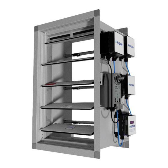
Model: AIRFLOW-IQ
Electronic Air Measuring Station with BACnet
Actuator and Class 1A Damper
ALL STATED SPECIFICATIONS ARE SUBJECT TO CHANGE WITHOUT PRIOR NOTICE OR OBLIGATION
Airflow-IQ Start-up & Commissioning Guide
II-AIRFLOW-IQ 718/Replaces II-AIRFLOW-IQ 418
©Ruskin July 2018
1
Advertisement
Table of Contents

Related Manuals for Ruskin AIRFLOW-IQ


Summary of Contents for Ruskin AIRFLOW-IQ
- Page 1 Start-up & Commissioning Guide Model: AIRFLOW-IQ Electronic Air Measuring Station with BACnet Actuator and Class 1A Damper ALL STATED SPECIFICATIONS ARE SUBJECT TO CHANGE WITHOUT PRIOR NOTICE OR OBLIGATION Airflow-IQ Start-up & Commissioning Guide II-AIRFLOW-IQ 718/Replaces II-AIRFLOW-IQ 418 ©Ruskin July 2018...
-
Page 2: Table Of Contents
AIRFLOW-IQ Electronic Air Measuring Station with BACnet Actuator and Class 1A Damper Table of Contents Product Application . . . . . . . . . . . . . . . . . . . . . . . . . . . . . . . . . . . . . . . . . . . . . . . . . . . . . . . . . . . . . . . . . .3 General Information . -
Page 3: Product Application
15 TDP05K Ancillary probe(s) . The Primary Display is configured at the factory with customer supplied All Airflow-IQ systems are supplied with a TDP05K Primary Display that is factory wired and may be connected to parameters . For normal applications the Primary Display’s configuration should not need to be modified in the up to 15 TDP05K Ancillary probe(s). -
Page 4: Electrical Guidelines
WARNING: Risk of Electric Shock severe personal injury or death. on new Confirm power requirements before wiring actuator . Ruskin is not responsible for any damage to, or failure of ectrical connections. Contact with ce that Confirm power requirements before wiring actuator. Ruskin is not responsible for any damage to, or failure of... -
Page 5: Receiving, Handling And Installation Guidelines
Remove the AIRFLOW-IQ from its shipping container and inspect for damage, rust or corrosion . Care must be taken in handling the unit . Always handle the AIRFLOW-IQ by its frame . Do not lift it by the blade, linkage, axle, motor or jackshaft . -
Page 6: Construction Details
(304 x 304 mm) size. FACE VIEW DAMPER SIDE Round Duct Mounting Attach Round Duct Hinge Plate to Round Duct Mounting Plate. Figure 1 TDP05K Advanced Thermal Dispersion Probe Airflow Measuring System Installation Instructions Airflow-IQ Start-up & Commissioning Guide Airflow-IQ Start-up & Commissioning Guide... -
Page 7: Ideal Installations Air Measurement Station Placements
Ruskin representative for the best solution . The locations TDP05K ADVANCED THERMAL DISPERSION AIRFLOW shown on these details represent the minimum clearance from most obstruction that create an airflow disturbance . - Page 8 5000 FPM, unless a different value was specified at the time the unit was ordered . Flow Control Mode: To operate the Airflow-IQ as a modulating damper, change the DamperMode BACnet data point (see Table 1) from CurrentAirflow to DamperPosition .
-
Page 9: Actuator Product Description
Field power wiring: use 18 ga wire, or 16 ga if over 25/ Airflow-IQ Start-up & Commissioning Guide... - Page 10 Ruskin Air Measurement Actuator (VAFB24-BAC) factory installed on TDP05K050/060 MODE OF OPERATION The air measurement actuator is the BACNET interface and setup port for the air measurement station . The air measurement actuator accepts an analog 0-10V signal via S2 input or a network driven CFM SETPOINT and will modulate the damper based on measured CFM to get to desired air flow .
-
Page 11: Log On To Actuator
Actuator’s IP address: 192 .168 .0 . 1 0:8080 Then click on the login button showing User Name: admin Password: rusnimda This will bring up the configuration screen for the Air Measurement Actuator shown on page 12 . Airflow-IQ Start-up & Commissioning Guide... -
Page 12: Webserver Screenshots
Ruskin VAFB24-‐BAC RAMS Actuator WEB Interface Ruskin VAFB24-BAC RAMS Actuator WEB Interface Ruskin VAFB24-‐BAC RAMS Actuator WEB Interface Actuator Reads Velocity Pressure from DP Sensor Actuator Reads Velocity Pressure from DP Sensor Velocity Pressure is Converted to Flow Rate (PAMS Chart) ... -
Page 13: Bacnet Object List
BO – Binary Output BV – Binary Value MI – Multi-State Input MO – Multi-State Output MV – Multi-State Value R – ReadOnly W – Writable C – Commandable (Contains Priority Array) Example 1: Example 2: Example 3: Airflow-IQ Start-up & Commissioning Guide... -
Page 14: Actuator Product Description
HVAC control applications . MP-Bus master capabilities allow this device to monitor and control up to 15 additional slave devices that contain Ruskin MP-Bus technology, affording significant expandability . BACnet server functionality allows easy integration in standard building auto- mation systems . -
Page 15: Bacnet Object Processing
The properties Object_Name and Location of the Device Object support up to 255 characters (all other character strings are read-only) . • The device does not support the CreateObject and DeleteObject service. Service Processing • The device supports DeviceCommunicationControl service. No password is required. Airflow-IQ Start-up & Commissioning Guide... - Page 16 Wiring All Airflow-IQ Stations are supplied with a Ruskin TDP05K primary probe that is factory wired to one or more TDP05K air measurement probe(s) . The primary probe was configured at the factory with customer supplied parameters . For normal applications the configuration stored in the primary probe should not need to be changed in the field .
- Page 17 Note: The Shield is connected on one end of each wire run and should never be connected on both ends of one wire . TDP05K Advanced Thermal Dispersion Probe Airflow Measuring System Installation Instructions TDP05K Advanced Thermal Dispersion Probe Airflow Measuring System Installation Instructions Airflow-IQ Start-up & Commissioning Guide Ruskin—CONFIDENTIAL Ruskin—CONFIDENTIAL...
- Page 18 Confirm the connections are made to the probe network are not to the http://www .ruskin .com/catalog/servefile/id/6767 for detailed configuration instructions . BACnet or analog output connections on the primary probe. After the device warms up, the temperature and flow readings display.
-
Page 19: Control Damper Information
. Regular maintenance should include periodic testing of all equipment associated with the air control system such as initiating devices, fans, dampers, controls, etc . Ruskin recommends each damper be cy- cled and tested every 6 months and in accordance with local codes and actuator manufacture recommendations (if damper has actuator) . -
Page 20: Menu Structure
. Output 1 mA High Span Output 2 mA Offset Output 2 mA Low Span Output 2 mA High Span Design Range Low Design Range High Temperature Range Low Temperature Range High Airflow-IQ Start-up & Commissioning Guide... - Page 21 Supervisor Menu Submenus Submenu Function Submenu Selections (Actual Display Name) Enable Supervisor PIN Enables PIN protection for the Supervisor Menu (Enable Supv PIN) Change Supervisor PIN Allows the user to update the PIN (Change Supv PIN) Airflow-IQ Start-up & Commissioning Guide...
-
Page 22: Troubleshooting
. Look at drawings and make sure left correct point or wrong connector and right are not swapped . No BACnet communication with the BAS Verify configuration parameters match what Not Configured correctly is required to communicate with the BAS Airflow-IQ Start-up & Commissioning Guide... -
Page 23: Maintenance
Repair Information for TDP05K If the TDP05K Advanced Thermal Dispersion Probe Airflow Measuring System fails to operate within its specifica- tions, contact the nearest Ruskin representative . Maintenance Twice a year, scroll through the velocity and temperature values using the Supervisor Menu/Sensor Management/ Display Probe Data . -
Page 24: Specifications
Copyright 2018 Ruskin Manufacturing The information provided in this manual is believed to be complete and accurate . Ruskin Manufacturing is a manufacturer and supplier of equip- ment and, as such, is not responsible for the manner in which its equipment is used nor for infringement of rights of third parties resulting from such use .
Need help?
Do you have a question about the AIRFLOW-IQ and is the answer not in the manual?
Questions and answers