
Subscribe to Our Youtube Channel
Summary of Contents for MTS Systems SilentFlo 505G2 Series
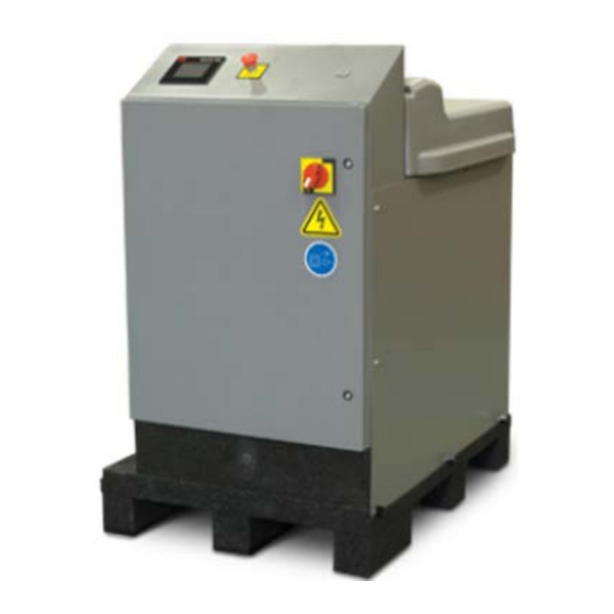
- Page 1 Series 505G2 SilentFlo™ Hydraulic Power Unit Model 505G2.07, Model 505G2.11 100-227-350 C...
- Page 2 Trac, Landmark, MAST, MicroProfiler, MPT, MTS Acumen, MTS Echo, MTS Fundamentals, MTS TestSuite, ReNew, SilentFlo, TempoGuard, TestLine, Tytron, Virtual Test Lab, and VTL are trademarks of MTS Systems Corporation within the United States. These trademarks may be registered in other countries. All other trademarks are the property of their respective holders.
-
Page 3: Table Of Contents
Contents Technical Support How to Get Technical Support Start with your manuals Technical support methods Outside the U.S. Before You Contact MTS Know your site (if applicable) and system numbers Know information from prior technical assistance Identify the problem Know relevant computer information Know relevant software information If You Contact MTS by Phone Identify system type... - Page 4 Contents Heat exchanger Auto-Cooling Valve (adjustable) Electrical Control Safety General Safety Practices: Hydraulic Power Units and Hydraulic Service Manifolds Read all manuals Locate and read hazard placards/labels Specimen temperature changes Know facility safe procedures Know controls Have first aid available Know potential crush and pinch points Be aware of component movement with hydraulics off Know electrical hazards...
- Page 5 Contents HPU Setup Operation Operator’s Panel Main Screen Status Screen Operating the HPU Locally or Remotely Recovering from an Interlock Changing the Water Flow Resetting the Thermal Overloads and Circuit Breakers Adjusting the Hydraulic Pressure Adjusting the HPU Output Pressure Level Auto-Cooling Valve (adjustable) Low/High Pressure Functionality Maintenance...
- Page 6 Contents 8 Hours/Daily 40 Hours/Weekly 160 Hours/Biweekly 500 Hours 1000 Hours 2000 Hours 5000 Hours 10,000 Hours Appendix B: Declaration of Conformity Example Series 505G2 SilentFlo™ Hydraulic Power Unit...
-
Page 7: Technical Support
Technical Support Technical Support How to Get Technical Support Start with your manuals The manuals supplied by MTS provide most of the information you need to use and maintain your equipment. If your equipment includes software, look for online help and README files that contain additional product information. -
Page 8: Know Information From Prior Technical Assistance
Technical Support Know information from prior technical assistance If you have contacted MTS about this problem before, we can recall your file based on the: MTS case number Name of the person who helped you Identify the problem Describe the problem and know the answers to the following questions: How long and how often has the problem occurred? Can you reproduce the problem? Were any hardware or software changes made to the system before the problem started? -
Page 9: If You Contact Mts By Phone
Technical Support If You Contact MTS by Phone A Call Center agent registers your call before connecting you with a technical support specialist. The agent asks you for your: Site number (if applicable) Email address Name Company name Company address Phone number where you can be reached If your issue has a case number, please provide that number. -
Page 10: After You Call
Technical Support After you call MTS logs and tracks all calls to ensure that you receive assistance for your problem or request. If you have questions about the status of your problem or have additional information to report, please contact Technical Support again and provide your original case number. Problem Submittal Form in MTS Manuals Use the Problem Submittal Form to communicate problems with your software, hardware, manuals, or service that are not resolved to your satisfaction through the technical support process. -
Page 11: Preface
Preface Preface Before You Begin Safety first! Before you use your MTS product or system, read and understand the safety information provided with your system. Improper installation, operation, or maintenance can result in hazardous conditions that can cause severe personal injury or death, or damage to your equipment and specimen. Again, read and understand the safety information provided with your system before you continue. -
Page 12: Other Special Text Conventions
Preface Other special text conventions Important: Important notices provide information about your system that is essential to its proper function. While not safety-related, if the important information is ignored, test results may not be reliable, or your system may not operate properly. Note: Notes provide additional information about operating your system or highlight easily overlooked information. -
Page 13: Introduction
Introduction Introduction Overview EU Declarations Intended Use Product Information CD Component Identification Functional Description Auto-Cooling Valve (adjustable) Electrical Control Series 505G2 SilentFlo™ Hydraulic Power Unit... -
Page 14: Overview
Introduction Overview The MTS Model 505.07 Hydraulic Power Unit (HPU) and Model 505.11 HPU provide high-pressure hydraulic fluid for test system operation. This section contains general information about the HPU. EU Declarations EC Declaration of Conformity (Machinery Directive 2006/42/EC Annex II 1A) If applicable, a Declaration of Conformity is supplied with the machinery;... -
Page 15: Component Identification
Introduction Drawing Description Number 700005313 Product Specifications 100025526 Series 505 SilentFlo™ HPU Lift and Move Instructions 700005263 505.07 Configuration Drawing 700000263 505.07 Hydraulic schematic 700004937 505.07 small PLC Electrical Schematic (200 - 480 VAC) 700005213 505.07 large PLC Electrical Schematic (200 - 480 VAC) 700004942 505.07 small PLC Electrical Schematic (575 VAC) - Page 16 Introduction Component Descriptions (part of ) Item Component Description Output Pressure Gage Displays the hydraulic pressure being output from the HPU. Auto-Cooling Valve Keeps the hydraulic fluid clean and cool by circulating the fluid through the return filter and the heat exchanger while the HPU is in high pressure mode and the fluid demand by the external circuit is very low.
- Page 17 Introduction Item Component Description Filler Cap Vents the hydraulic fluid reservoir. This is where you add hydraulic fluid. Reservoir Holds the hydraulic fluid and houses the hydraulic pump and motor. The surge suppressor (optional) is mounted to the pump. Hydraulic and Water Connection points for the hydraulic fluid distribution system, Connections water source, and return lines.
-
Page 18: Functional Description
Introduction Item Component Description Hazard placards Hazard placards contain specific safety information and are affixed directly to the system so they are plainly visible. Each placard describes a product-related hazard. When possible, international symbols (icons) are used to graphically indicate the type of hazard and the placard label indicates its severity. -
Page 19: Heat Exchanger
Introduction Heat exchanger Hydraulic fluid temperature is maintained with a heat exchanger that cools the fluid. The water-cooled heat exchanger cools the hydraulic fluid as it passes over water-filled plates. A regulating valve monitors the temperature of the hydraulic fluid and adjusts the flow of water through the plates. The flow of cooling water regulates the temperature of the hydraulic fluid. - Page 20 Introduction A Reset button brings the unit back into operation after a fault has been detected and corrected. A dirty filter signal will not shut the unit down, but will prevent the unit from starting. The power disconnect switch on the door of the main electrical enclosure ensures that power is removed whenever the door is opened.
-
Page 21: Safety
Safety Safety General Safety Practices: Hydraulic Power Units and Hydraulic Service Manifolds Series 505G2 SilentFlo™ Hydraulic Power Unit... -
Page 22: General Safety Practices: Hydraulic Power Units And Hydraulic Service Manifolds
Safety General Safety Practices: Hydraulic Power Units and Hydraulic Service Manifolds The hydraulic power unit (HPU) provides high pressure hydraulic fluid to system components for system operation. The hydraulic service manifold (HSM) controls distribution of that hydraulic fluid pressure. This section provides general information about safety issues that pertain to system hydraulic supply and distribution components. -
Page 23: Read All Manuals
Safety learn and identify hazards so that you can establish appropriate training and operating procedures and acquire appropriate safety equipment (such as gloves, goggles, and hearing protection). Each test system operates within a unique environment which includes the following known variables: Facility variables (facility variables include the structure, atmosphere, and utilities) Unauthorized customer modifications to the equipment Operator experience and specialization... -
Page 24: Have First Aid Available
Safety Have first aid available Accidents can happen even when you are careful. Arrange your operator schedules so that a properly trained person is always close by to render first aid. In addition, ensure that local emergency contact information is posted clearly and in sight of the system operator. Know potential crush and pinch points Be aware of potential crush and pinch points on your system and keep personnel and equipment clear of these areas. -
Page 25: Check Bolt Ratings And Torques
Safety Check bolt ratings and torques To ensure a reliable product, fasteners (such as bolts and tie rods) used in MTS-manufactured systems are torqued to specific requirements. If a fastener is loosened or the configuration of a component within the system is modified, refer to information in this product manual to determine the correct fastener, fastener rating, and torque. -
Page 26: Use Appropriately Sized Fuses
Safety Use appropriately sized fuses Whenever you replace fuses for the system or supply, ensure that you use a fuse that is appropriately sized and correctly installed. Undersized or oversized fuses can result in cables that overheat and fuses that explode. Either instance creates a fire hazard. Provide adequate lighting Ensure adequate lighting to minimize the chance of operation errors, equipment damage, and personal injury. -
Page 27: Ensure Secure Cables
Safety Ensure secure cables Do not change any cable connections when electrical power or hydraulic pressure is applied. If you attempt to change a cable connection while the system is in operation, an open control loop condition can result. An open control loop condition can cause a rapid, unexpected system response which can result in severe personal injury, death, or damage to equipment. - Page 28 Safety When you charge an accumulator, follow all the charging instructions provided in the appropriate product information manuals. When precharging accumulators, properly identify the type of gas to be used and the type of accumulator to be precharged. Use only dry-pumped nitrogen to precharge nitrogen-charged accumulators. (Dry-pumped nitrogen can also be labeled “oil pumped”...
- Page 29 Safety Label Description Hydraulic Power Unit information label. Part # 100-263-702 Caution To prevent equipment damage and impede performance, remove red shipping plug under filler cap before operating. Replace with black plastic snap in strainer. Part # 050-174-101 Voltage hazard. High voltage exists in the vicinity where this icon is located.
- Page 30 Safety Label Description protection. Maintain safe pressure levels. Disconnect from electrical power before servicing. Read the manuals. Wye-Delta Connections Use for single voltage 6 lead motors suitable for wye-delta starting. Part # 053-448-401 Series 505G2 SilentFlo™ Hydraulic Power Unit...
-
Page 31: Installation
Installation Installation Install the HPU HPU Setup Series 505G2 SilentFlo™ Hydraulic Power Unit... -
Page 32: Install The Hpu
Installation This section describes how to install the Series 505 Hydraulic Power Unit (HPU). The HPU is designed for indoor use. The HPU should be stored and installed indoors. Install the HPU 1. Position the hydraulic power unit. Determine where to put the HPU. Review the following: The HPU can fit through a standard 1-m or 36-in door. - Page 33 Installation B. Connect the grounding wire to the lug labeled PE GND (protective earth ground). 3. Connect the hydraulic lines. The following figure shows the hydraulic adapter ports to the HPU. Note: Each hydraulic connection requires an O-ring face seal. 4.
- Page 34 Installation Water Inlet Model 505.07 Model 505.11 Temperature 10.0°C (50°F) 3.8 L/m (1.0 gpm) 7.2 L/m (1.9 gpm) 15.5°C (60°F) 4.9 L/m (1.3 gpm) 9.1 L/m (2.4 gpm) 21.1°C (70°F) 6.1 L/m (1.6 gpm) 12.1 L/m (3.2 gpm) 26.7°C (80°F) 8.3 L/m (2.2 gpm) 18.9 L/m (5.0 gpm) 32.2°C (90°F) 15.9 L/m (4.2...
-
Page 35: Hpu Setup
Installation G. Verify the correct output pressure, as shown on the pressure gage. H. Press the Stop button to shut down the unit. 6. Connect the controller cable (if used). The controller cable provides a means to connect your controller to the HPU. When connected, your controller can remotely start and stop the unit and switch between the low and high pressure selections. - Page 36 Installation Setup HMI (human-machine interface) screen. 5. The following table describes the pushbuttons and indicators on the Setup screen. Name and Description Location Use Buttons Below Indicator - blue-green: Provides instruction for the setup screen. To Change Parameters Remote Fault Pushbutton /Indicator.
- Page 37 Installation Name and Description Location One of the auxiliary contacts can be used to control an external device such as a warning lamp or a remote cooling circuit. The auxiliary contact controls whether the contact is active whenever a pump motor is running (Aux Contact: On/Off - gray) or whenever a pump motor is running and the temperature of the hydraulic fluid in the reservoir reached the trip temperature (Aux Contact: Temp - black).
- Page 38 Installation Name and Description Location Pressure Filter Not Pushbutton /Indicator. This button is used to define if a pressure filter is Present/Pressure present. Filter Present Pressure Filter Not Present- gray: The HPU does not have a pressure filter. Pressure Filter Present- black: The HPU does have a pressure filter. Temp Display In Pushbutton/Indicator: Used to select temperature display in either (deg)
-
Page 39: Operation
Operation Operation Operator’s Panel Series 505G2 SilentFlo™ Hydraulic Power Unit... -
Page 40: Operator's Panel
Operation This section describes the front panel controls and indicators, and provides operating instructions for the Series 505 Hydraulic Power Unit (HPU). Operator’s Panel Main Screen The Main screen is displayed initially when the HPU is powered up. The following table describes the pushbuttons and indicators on the Main screen. - Page 41 Operation Name and Location Description Faulted/Ready/Running/High Indicator. Indicate the various state of the HPU Pressure/Alarm/Overtemp Faulted - red: Initial condition. Also displayed when an Bypass interlock has occurred and the HPU has been shut down. Ready - green: Indicates the interlocks are cleared and the HPU is ready to start.
- Page 42 Operation Name and Location Description operation. Remote Operation - gray: Indicates the HPU is not in remote operation. Remote Operation - green: Indicates the HPU is in remote operation. In remote operation, the local Run and High Pressure buttons are disabled Pump Hours Indicator/Display: Indicates total running time of the HPU.
-
Page 43: Status Screen
Operation Name and Location Description Main Pushbutton/Indicator. Pushbutton used to select the Main screen. Main - gray: In this state, one of the other screens is selected; for example the Status screen. Main - black: The Main screen is selected and displayed. Status Pushbutton/Indicator. - Page 44 Operation Name and Location Description Watchdog Indicator. Used to indicate the status of the watchdog timer. OK/Watchdog Fault Watchdog OK - gray: Indicates the PLC that controls the HPU is operating normally. Watchdog Fault - red: Indicates there is a problem with the hardware watchdog timer and the PLC is not operating correctly.
-
Page 45: Operating The Hpu Locally Or Remotely
Operation Name and Location Description Motor Overload- red: Indicates the pump motor has overheated and an interlock is active. Motor Sequence Indicator. Used to indicate if the pump motor sequence is operating OK/Motor Sequence properly. Fault Motor Sequence OK - gray: Indicates the motor sequence is not in a fault condition and operating properly. - Page 46 Operation Local operation 1. Make a general inspection of the HPU. Ensure that all cooling water valves are open. Ensure the Emergency Stop button is released. 2. If not already displayed, press the Main button to display the Main screen. 3.
-
Page 47: Recovering From An Interlock
Operation Recovering from an Interlock This section describes how to reset each type of HPU interlock. If a fault occurs (Low Level, Over temperature, Dirty Filter), the HPU will not start. You must determine the source of the interlock and correct the cause before using the HPU. -
Page 48: Changing The Water Flow
Note: When the HPU is turned off, a solenoid valve also shuts off the flow of water to the heat exchanger. The water-regulating valve is adjusted at MTS Systems Corporation to maintain the hydraulic fluid temperature at 43°C (110°F). However, the temperature of your water may require you to readjust the regulator. -
Page 49: Resetting The Thermal Overloads And Circuit Breakers
Operation To set the operating temperature of the hydraulic fluid: 1. Start the HPU and switch to high-pressure mode. 2. Observe the temperature gage as the hydraulic fluid temperature rises. Note the temperature where the hydraulic fluid stabilizes. 3. Adjust the water-regulating valve. One full turn (360°) of the adjusting screw produces a change in hydraulic fluid temperature a few degrees. -
Page 50: Adjusting The Hydraulic Pressure
Operation 3. Locate the tripped thermal overload or circuit breaker; labeling is provided next to each component for identification. If necessary, press Reset to clear the switch. If the thermal overload or circuit breaker switch trips again after the cause has been remedied, wait until the switch/breaker cools. -
Page 51: Adjusting The Hpu Output Pressure Level
Operation Adjusting the HPU Output Pressure Level 1. Turn on high hydraulic pressure. Ensure that there are no flow demands by the system. 2. Loosen the nut securing the output pressure control. 3. Monitor the hydraulic pressure gage located on the control manifold. Adjust the output pressure as follows until the desired pressure is displayed. - Page 52 Operation The following procedure assumes that Steps 1 through 3 of “Adjusting the HPU output pressure level” have already been completed. 1. With the HPU running in high, loosen the nut on the Auto-Cooling Valve located on the control manifold (see the previous figure). 2.
- Page 53 Operation 6. Hold the HPU Output Pressure Control to prevent it from turning while tightening the nut. 7. Verify that the output pressure remained at the desired level and tighten the nut to secure the setting. A. Hold the Auto-Cooling Valve stem to prevent it from turning while tightening the nut. Adjusting the Auto-Cooling Valve if the HPU shuts down due to an over-temperature condition or if the HPU fails to deliver the full flow to the external circuit.
-
Page 54: Low/High Pressure Functionality
Operation 5. If necessary, repeat steps 2 and 3 until the Auto-Cooling Valve is stable and the HPU cools properly. 6. After the final adjustment, hold the HPU Output Pressure Control to prevent it from moving while tightening the nut to secure the setting. 7. - Page 55 Operation Keeping the HPU in low pressure effectively isolates the external or system flow because the relative back pressure is normally much higher in the external system circuit. Running the HPU in low pressure maximizes fluid flow, allowing the HPU to circulate the reservoir contents across the filter more times per hour.
- Page 56 Operation High pressure When the Series 505 HPUs are running in high pressure, a considerable amount of heat is generated. During normal testing, this heat is dissipated by running the hydraulic fluid through the system from the return line to the heat exchanger. During periods of low system demand, this heat is dissipated by running the hydraulic fluid through the auto-cooling circuit to the heat exchanger.
-
Page 57: Maintenance
Maintenance Maintenance Before You Begin Routine Maintenance Overview Checklist Series 505G2 SilentFlo™ Hydraulic Power Unit... -
Page 58: Before You Begin
Maintenance Before You Begin Spare parts Parts that are specified in the maintenance procedures of this section can be obtained from MTS Systems Corporation. Lockout/tagout For your safety, follow all appropriate lockout/tagout procedures while performing HPU maintenance. Operating the HPU When running the HPU, become familiar with the sounds and smells of the HPU. - Page 59 Maintenance Calendar Time using 8 hour Daily Weekly Monthly Annually Running Time rate per day Running Time- 1000 1,500 2,000 5,000 10,000 Hours Check cables and connectors Check console air filter Check all MTS MTS MTS accumulators for proper precharge pressure and oil Check condition MTS MTS MTS...
- Page 60 Maintenance Calendar Time using 8 hour Daily Weekly Monthly Annually Running Time rate per day Running Time- 1000 1,500 2,000 5,000 10,000 Hours hoses for leaks Lubricate- MTS MTS MTS grease motor bearings (non 505) Verify dirty filter MTS MTS MTS indicators status Verify HPU MTS MTS MTS...
-
Page 61: Checking The Hydraulic Fluid
Maintenance Calendar Time using 8 hour Daily Weekly Monthly Annually Running Time rate per day Running Time- 1000 1,500 2,000 5,000 10,000 Hours replacement or rebuild of heat exchanger Recommend replacement of hoses Inspect motor bearings Determine if replacement or rebuild of pump ‡... -
Page 62: Replacing The Return Line Filter
Maintenance Important: To prevent problems with inconsistent and inferior fluids, MTS recommends only ExxonMobil DTE 25 or Shell Tellus 46 to its customers. Procedure Perform the following checks of the hydraulic fluid weekly. If you suspect contamination of the hydraulic fluid, take a sample and have it analyzed. - Page 63 Maintenance Prerequisite You will need a filter element (MTS part number 100-009-495) or a filter kit (MTS part number 100- 030-195). Procedure To change the filter element: Note: The dirty-filter indicator may light when the HPU is first started due to low hydraulic fluid temperature.
-
Page 64: Sample The Hydraulic Fluid
If leakage occurs, repeat this procedure (without replacing the filter element). If leakage persists, contact MTS Systems Corporation. 10. If you are changing the filter because the dirty filter indicator tripped, run the HPU for two to four hours to remove contaminants. - Page 65 Maintenance Hold the hose valve assembly still when taking a sample. Do not let the hose sample assembly line touch the mouth of the bottle or go into the bottle. Prerequisite You will need a hydraulic fluid sampling kit (part number 055-589-601). Procedure Take a fluid sample from the reservoir to get a visual indication of the fluid level and relative contamination.
-
Page 66: Appearance Of Hydraulic Fluid Sample
7. If there still is any uncertainty regarding fluid quality, obtain another sample of the fluid and have it analyzed. The fluid tests should include chemical analysis, particle count, and viscosity checks. Most oil companies have facilities for performing these tests, or consult MTS Systems Corporation. -
Page 67: Replacing The Hydraulic Fluid
Maintenance Fluid Problem What to Do Properties Milky Indicates water is present in Check the heat exchanger for damage. appearance the fluid Look for other water sources if the water does not appear to be coming from the heat exchanger. Identify and correct the source of the water leakage and replace the fluid if necessary. - Page 68 Mixing different brands of hydraulic fluid can contaminate your system. Contaminated hydraulic fluid can cause premature wear of the hydraulic components in your system. Do not mix different brands of hydraulic fluid. MTS Systems Corporation recommends using ExxonMobil DTE-25 or Shell Tellus 46 AW hydraulic fluid. Procedure See “Component Identification”...
- Page 69 Maintenance D. Press the Stop button. E. Check the dirty filter indicator. Replace the filter element as needed. Series 505G2 SilentFlo™ Hydraulic Power Unit...
-
Page 71: Accessories
Accessories Accessories High Pressure Filter Kit Surge Suppressor Kit Precharging the Surge Suppressor Accumulator Lifting Kit Caster Kit Series 505G2 SilentFlo™ Hydraulic Power Unit... -
Page 72: High Pressure Filter Kit
Accessories High Pressure Filter Kit This section describes how to install the high pressure filter kit (part number 100-008-737). To install the high pressure filter kit: 1. Ensure that system hydraulic pressure has been reduced to zero before proceeding. To do this, turn off the hydraulic power unit and exercise the actuator until it stops moving. -
Page 73: Surge Suppressor Kit
Accessories 1. Ensure that system hydraulic pressure has been reduced to zero before proceeding. To do this, turn off the hydraulic power unit and exercise the actuator until it stops moving. 2. Unscrew the filter bowl and remove the filter element. 3. -
Page 74: Installation Procedure
Accessories A Model 505.07 Surge Suppressor kit (part number 100-008-667) or a Model 505.11 Surge Suppressor kit (part number 100-008-665). Optional Remote Charging kit (part number 100-056-912) A transfer pump with a 10-micron filter (such as the Model 590.01 Fluid Transfer Pump). A cleaning solvent such as ethanol. -
Page 75: Precharging The Surge Suppressor Accumulator
Accessories Precharging the Surge Suppressor Accumulator It is normal for a small amount of surge suppressor precharge loss to occur during operation. Because of this gradual reduction in precharge pressure, the pressure should be checked and recharged (if necessary) at regular intervals. Determining a pressure check interval The precharge pressure checking intervals of your surge suppressor depends on how your system is used. -
Page 76: Changing The Precharge Pressure
Accessories Changing the precharge pressure The nitrogen precharge should be within the range of 10.3–12.5 MPa (1500–1800 psi) which is 50– 60% of the output pressure (21 MPa or 3000 psi). Perform one of the following procedures to change the precharge pressure. Decreasing pressure To decrease the precharge pressure: 1. -
Page 77: Lifting Kit
Accessories 6. Slowly open the regulator shut-off valve until gas is heard escaping from the accumulator charging kit bleed valve. A. Allow gas to slowly escape for approximately ten seconds, and then close the bleed valve. B. Immediately close the regulator shut-off valve before the pressure reading on either the high or low charging kit pressure gage exceeds the pressure level of the accumulator. -
Page 78: Caster Kit
Accessories Lifting Support Brackets and Slings Caster Kit The caster kit (part number 100-025-327) is a couple of channel supports with casters (two rigid, two locking swivel) connected by support angle brackets. The caster kit allows the hydraulic power unit to be easily moved. - Page 79 Accessories Caster Kit Series 505G2 SilentFlo™ Hydraulic Power Unit...
-
Page 81: Appendix A: Hpu Maintenance And Service Logs
Appendix A: HPU Maintenance and Service Logs Appendix A: HPU Maintenance and Service Logs 8 Hours/Daily 40 Hours/Weekly 160 Hours/Biweekly 500 Hours 1000 Hours 2000 Hours 5000 Hours 10,000 Hours Series 505G2 SilentFlo™ Hydraulic Power Unit... -
Page 82: Hours/Daily
Appendix A: HPU Maintenance and Service Logs 8 Hours/Daily 8 Hours/Daily Service Interval Recommendation Check Console Check Dirty Check for Check oil Check Verification Filter Indicators Leaks Level Pressure Performed Performed Performed Date Performed by Performed by Notes 40 Hours/Weekly Series 505G2 SilentFlo™... -
Page 83: 160 Hours/Biweekly
Appendix A: HPU Maintenance and Service Logs 40 Hours/Weekly Service Interval Recommendation Check Fluid Color and Odor Check Interlock Devices Date Performed by Performed by Notes 160 Hours/Biweekly 160 Hours/Monthly Service Interval Recommendation Check Cables and Connectors Check Console Air Filter Date Performed by Performed by... -
Page 84: 500 Hours
Appendix A: HPU Maintenance and Service Logs Check Cables and Connectors Check Console Air Filter Date Performed by Performed by Notes 500 Hours 500 Hours Service Interval Recommendation Inspect Check All Check Check Clean Check HPU Heat Accumulators Condition of Control Operating Exchanger... -
Page 85: 1000 Hours
Appendix A: HPU Maintenance and Service Logs 500 Hours Service Interval Recommendation Verify Dirty Inspect Pump Lubricate-Grease Verify HPU Verify Warning Filter Hoses for motor Bearings Hydraulic and Interlock Indicators Leaks (non-505) Fluid Level Devices Status Date Performed by Performed by Performed by Performed by Performed by... -
Page 86: 2000 Hours
Appendix A: HPU Maintenance and Service Logs All 500 hr Replace All Verify Operation and Settings of psi Maintenance Filters Control and Relief Valves Procedures Performed Date Performed by Performed by Notes 2000 Hours 2000 Hours Service Interval Recommendation Check Check All 1000 hr Check... -
Page 87: 5000 Hours
Appendix A: HPU Maintenance and Service Logs Check Check All 1000 hr Check Recommend Pump/Motor Pump Maintenance Case Drain MTS Hydraulix Coupling for Voltage and Procedures Flow Oil Sample Wear and Debris Current Performed Performed Date Performed by Performed by Performed by Notes 5000 Hours... - Page 88 Appendix A: HPU Maintenance and Service Logs 10,000 Hours Service Interval Recommendation Recommend Determine if Determine if Hydraulic Recommend Recommend Inspect Replacement Replacement Fluid R/R Heat Replacement Motor or Rebuild of or Rebuild of Change & Exchanger of Hoses Bearings Pump Motor Clean Pump...
-
Page 89: Appendix B: Declaration Of Conformity
Appendix B: Declaration of Conformity Appendix B: Declaration of Conformity Example Series 505G2 SilentFlo™ Hydraulic Power Unit... -
Page 90: Example
Appendix B: Declaration of Conformity Example Series 505G2 SilentFlo™ Hydraulic Power Unit... - Page 91 Appendix B: Declaration of Conformity Series 505G2 SilentFlo™ Hydraulic Power Unit...
- Page 94 MTS Systems Corporation 14000 Technology Drive Eden Prairie, Minnesota 55344-2290 USA Toll Free Phone: 800-328-2255 (within the U.S or Canada) Phone: 952-937-4515 (outside the U.S. or Canada) E-mail: info@mts.com Internet: www.mts.com ISO 9001 certified QMS...
Need help?
Do you have a question about the SilentFlo 505G2 Series and is the answer not in the manual?
Questions and answers