Table of Contents
Advertisement
Quick Links
Advertisement
Table of Contents

Summary of Contents for JRC JLN-720
- Page 1 General Function of Each Components Operation Method Menu Settings and Configurations Installation Method JLN-720 Maintenance and Inspection After-Sales Service Disposal SATELLITE LOG Specification APP A Installation Drawings Instruction Manual APP B Spare Parts List...
- Page 3 Safety Cautions Cautions for High Voltage High voltage of hundreds volts is used inside this equipment. Touching a component inside the unit is very dangerous. (Any person other than authorized service engineers should not maintain, inspect, or adjust the unit.) High voltages on the order of tens of thousand volts are most likely to cause instant deaths from electrical shocks.
-
Page 4: Emergency Measures
Emergency Measures Method of First-Aid Treatment Precautions for First-Aid Treatments Apply artificial respiration to the person who collapsed, minimizing moving as much as possible avoiding risks. Once started, artificial respiration should be continued rhythmically. (1) Refrain from touching the patient carelessly as a result of the accident; the first-aider could suffer from electrical shocks by himself or herself. - Page 5 Treatment to Give When the Patient Has a Pulse Beating but Has Ceased to Breathe ∗ Performing mouth-to-mouth artificial respiration (1) Bend the patient's face backward until it is directed to look back. (A pillow may be placed under the neck.) (2) Pull up the lower jaw to open up the airway.
- Page 6 Flow of Cardiopulmonary Resuscitation (CPR) A person is collapsing. A person is collapsing. - Secure the safety of the surrounding area. - Secure the safety of the surrounding area. - Prevent secondary disasters. - Prevent secondary disasters. Listen to the appeal of the Responding Check for response.
- Page 7 Specific Procedures for Cardiopulmonary Resuscitation (CPR) 1. Check the scene for safety to prevent secondary disasters Are you OK? a) Do not touch the injured or ill person in panic when an accident has occurred. (Doing so may cause electric shock to the first-aiders.) b) Do not panic and be sure to turn off the power.
- Page 8 b) If the injured or ill person is breathing, place him/her in the recovery position and wait for the arrival of the emergency services. • Position the injured or ill person on his/her side, maintain a clear and open airway by pushing the head backward while positioning their Roll gently in the opposite mouth downward.
- Page 9 2) Perform chest compressions Compress with these • Perform uninterrupted chest compressions of 30 parts (the heels of at the rate of about 100 times per minute. both hands). While locking your elbows positioning yourself vertically above your hands. • With each compression, depress the chest wall to a depth of approximately 4 to 5 cm. b) Combination of 30 chest compressions and 2 rescue breaths 30 times 1) After performing 30 chest compressions, give 2 rescue...
- Page 10 then paste the pads. If there is a pacemaker or implantable cardioverter defibrillator (ICD), paste the pads at least 3cm away from them. If a medical patch or plaster is present, peel it off and then paste the pads. If the injured or ill person's chest hair is thick, paste the pads on the chest hair once, peel them off to remove the chest hair, and then paste new pads.
- Page 11 16. When to stop CPR (Keep the electrode pads on.) a) When the injured or ill person has been handed over to the emergency services b) When the injured or ill person has started moaning or breathing normally, lay him/her on his/her side in a recovery position and wait for the arrival of emergency services.
- Page 12 (This page intentionally left blank)
-
Page 13: Table Of Contents
Contents Safety Cautions ......................i Emergency Measures ........................Contents ............................. Preface ............................... Pictorial Indication ..........................xvi Usage Precautions ........................... xvii Exterior of the Equipment xxiv ...................... Abbreviations ..........................Glossary xxviii ............................. Chapter 1 General ........................1-1 Functions......................... 1-1 Features .......................... 1-2 Components ........................ - Page 14 4.3.5 Advanced Settings ....................4-11 4.3.6 Setting the number of decimal digits of a ship speed ........... 4-11 4.3.7 Ship Speed Unit Settings ..................4-12 4.3.8 GPS Information and Settings ................4-13 4.3.8.1 Satellite Information..................4-14 4.3.8.2 Initial Settings ....................4-17 4.3.8.3 Smoothing Settings ..................
- Page 15 Remote Display (Optional) NWZ-650SDR ..............9-5 9.5.1 Panel ........................9-5 9.5.2 Electrical Specifications ................... 9-5 9.5.3 Environmental Requirements .................. 9-5 9.5.4 Mechanical Specifications ..................9-5 Remote Display (Optional) NWZ-840SDR ..............9-6 9.6.1 Panel ........................9-6 9.6.2 Electrical Specifications ................... 9-6 9.6.3 Environmental Requirements ..................
- Page 16 (This page intentionally left blank)
-
Page 17: Preface
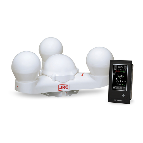
Preface Thank you for purchasing this JLN-720 Satellite Log from Japan Radio Co., Ltd.. This equipment is an SDME (Speed and Distance Measuring Equipment), complying with the regulations of IMO (International Marine Organization), measures and displays wide-range vessel speed over ground. -
Page 18: Pictorial Indication
Pictorial Indication Meanings of Pictorial Indication Various pictorial indications are included in this manual and are shown on this equipment so that you can operate them safely and correctly and prevent any danger to you and / or to other persons and any damage to your property during operation. -
Page 19: Usage Precautions
Usage Precautions DANGER Never remove the cover of this equipment. Touching the high-voltage section inside may cause an electric shock. Before conducting inspection, maintenance or parts replacement, make sure to turn off the power and breaker. Failure to comply may cause an electric shock, fire or an equipment fault. Make sure to turn the breaker off since voltage is still outputted from the distribution processor even after the displays are turned off. - Page 20 A fire, an electric shock, or a malfunction may occur. For maintenance, inspection of the internal section of the equipment, request the service to the store, nearest JRC agent, JRC marine service department, sales department, regional office, branch or sales office.
- Page 21 Failure to comply may result in an electric shock. When the power cable is damaged (exposed cable conductor, broken cable, or torn capsule), request replacement to the store, nearest JRC agent, JRC marine service department, sales department, regional office, branch or sales office.
- Page 22 Disposal of the battery must obey the local laws or rules. Before disposal of used lithium batteries, make sure the + and – terminals are insulated by tape. Otherwise, heat, rupture or fire may occur due to a battery short. When installing the cable that is attached to the GPS compass sensor, do not bend the cable to a sharp angle, twist it, or install it in such a manner that some force is applied to the cable.
- Page 23 Electrical work for this equipment must be requested to the store, nearest JRC agent, JRC marine service department, sales department, regional office, branch or sales office. Conducting electrical work by anyone other than the specialized maintenance staff may result in an accident or an equipment fault.
- Page 24 Do not use or leave the equipment under direct sunlight for a long time or in the temperatures above 55°C. (except wing display) Otherwise, fire or a malfunction may occur. Do not install the equipment in a place under the influence of water, humidity, vapor, dust or soot.
- Page 25 Do not carry out operation of touch panel by a sharp object. Otherwise, the screen may be damaged. If power outage occurs inside of the ship during the operation of the satellite log, the image may be disturbed or may not be displayed. In this case, reconnect the power supply.
-
Page 26: Exterior Of The Equipment
Exterior of the Equipment NWZ-510SDG Main Display NNN-21 GPS Compass Sensor NQA-7010 Distribution Processor xxiv... -
Page 27: Abbreviations
Abbreviations Alternating Current Acknowledge Advanced (Settings) Automated External Defibrillator Alarm approx. approximate(ly) AUTO Automatic Bit per Second Bottom Tracking BUZZ Buzzer Calibrate CALC Calculation Channel COMM Communication Cardiopulmonary Resuscitation Direct Current Display Dimming Control DGPS Differential GPS Dimmer DISP Display Dead Reckoning, Dead Reckoned Position Drawing East... - Page 28 Internet Protocol (Address) International Protection kn (current abbr.) knot kt (former abbr.) knot Live Wire Local Area Network (Cable) Liquid Crystal Display MANUAL Manual MENU Menu Medium Frequency Multi-information Display minute(s) Neutral Wire North Nautical Mile NMEA National Marine Electronics Association Number Personal Computer PORT...
- Page 29 Vector Track an Speed over the Ground (NMEA-Standard Sentence) West Water Tracking xxvii...
-
Page 30: Glossary
Glossary IEC60945 Maritime navigation and radiocommunication equipment and systems – General requirements – Methods of testing and required test results IEC61023 Maritime navigation and radiocommunication equipment and systems – Marine speed and distance measuring equipment (SDME) – Performance requirements, methods of testing and required test results IEC61162 Maritime navigation and radiocommunication equipment and... -
Page 31: Chapter 1 General
Chapter 1 General 1.1 Functions JLN-720 satellite log is equipment that receiving signals from GPS satellites by GPS compass sensor mounted on board, and then measures speeds over the ground (SOG) based on the signal. This equipment can measure and display the triaxial vessel speed, which are ahead/stern vessel speed, bow starboard/port speed, and stern starboard/port speed. -
Page 32: Features
1.2 Features This equipment has the following features. Color main display with touch panel This equipment contains a 5-inch color main display with touch panel to indicate maritime information, such as vessel speed, sailing distances. It has a user interface for making various settings. Triaxial vessel speed calculation Combining with GPS compass sensor, Gyro and ROT, this equipment can measure and display the triaxial vessel speed, which are ahead/stern vessel speed, bow starboard/port speed, and stern... - Page 33 Supported standards This equipment complies with the following standards. IMO MSC.334(90) IEC61023 ed.3 IEC60945 ed.4 IEC61162-1 ed.5 IEC61924-2 ed.1 INS-1 IEC62288 ed.2 Chapter 1 Outline of the Equipment...
-
Page 34: Components
1.3 Components The standard components and optional components (separately sold) are shown in the tables below. Standard components Item name Model Code Quantity Remarks GPS Compass Sensor NNN-21 NNN21CH Distribution Processor NQA-7010 NQA-7010 Main Display NWZ-510SDG NWZ510SDG 5-inch display Cable for communication Data Cable H-CFQ-7248 CFQ-7248... - Page 35 Item name Model Code Quantity Remarks Cable for communication / Remote Display power supply between the CFS-6680 CFS6680 Communication remote display and Cable Distribution Processor (1.2m) H-CFQ7248-30 CFQ7248-30 GPS Compass 30m / 14-core Sensor CFQ-7249 CFQ-7249 20m / 14-core / extension Connection H-CFQ-7249-10 CFQ7249-10...
-
Page 36: Construction
1.4 Construction This section provides the outline drawings of the system components. GPS Compass Sensor Weight: 5.9kg NNN-21 (Unit: mm) Distribution Processor Weight: 11kg NQA-7010 (Unit: mm) Chapter 1 Outline of the Equipment... - Page 37 Main Display Weight: 1.2kg NWZ-510SDG (Unit: mm) Remote Display (Optional) Weight: 1.7kg NWZ-650SDR (Unit: mm) Chapter 1 Outline of the Equipment...
- Page 38 Remote Display (Optional) Weight: 2.4kg NWZ-840SDR (Unit: mm) Multi-information Display (Optional) Weight: 0.8kg NWZ-4610 (Unit: mm) Chapter 1 Outline of the Equipment...
- Page 39 Wing Display (Optional) Weight: 5kg NWW-61T (Unit: mm) Digital Display (Optional) Weight: 1.3kg NWW-62TB (Unit: mm) Chapter 1 Outline of the Equipment...
- Page 40 Distance Counter (Optional) Weight: 0.8kg NWW-7 (Unit: mm) Note The sailing distance meter NWW-7 operates up to a speed of 45 kn. Analog Display (Optional) NWW-24 (Unit: mm) Chapter 1 Outline of the Equipment 1-10...
- Page 41 NWW-25 (Unit: mm) NWW-26 (Unit: mm) 1-11 Chapter 1 Outline of the Equipment...
- Page 42 NWW-24 NWW-25 NWW-26 (Built-in) (Wall-mount) (Panel built-in) Range Size Green Orange Green Orange Green Orange NWW-24L20G NWW-24L20O NWW-25L20G NWW-25L20O NWW-26L20G NWW-26L20O NWW-26M20G NWW-26M20O NWW-24S20G NWW-24S20O NWW-25S20G NWW-25S20O NWW-26S20G NWW-26S20O NWW-24L25G NWW-24L25O NWW-25L25G NWW-25L25O NWW-26L25G NWW-26L25O NWW-26M25G NWW-26M25O NWW-24S25G NWW-24S25O NWW-25S25G NWW-25S25O NWW-26S25G NWW-26S25O NWW-24L30G NWW-24L30O NWW-25L30G NWW-25L30O NWW-26L30G NWW-26L30O...
- Page 43 Dimmer Unit (Optional) Weight: 0.5kg NCM-227 (Unit: mm) Distance counter (Optional) Weight: 0.5kg NCM-329 (Unit: mm) 1-13 Chapter 1 Outline of the Equipment...
-
Page 44: System Configuration
1.5 System Configuration Chapter 1 Outline of the Equipment 1-14... -
Page 45: Chapter 2 Function Of Each Components
Chapter 2 Function of Each Components 2.1 Main Display NWZ-510SDG ① ② Name Function Display • Displays the following information as a display. ① - Operation status of the equipment (normal/abnormal) - Ahead/astern speed, bow starboard/port speed, stern starboard/port speed - Section sailing distance/total sailing distance - Rate of turn (ROT) •... -
Page 46: Remote Display (Optional) Nwz-650Sdr/840Sdr
2.2 Remote Display (Optional) NWZ-650SDR/840SDR ① ② NWZ-650SDR (Digital) NWZ-650SDR (Analog) ① ② NWZ-840SDR (Digital) NWZ-840SDR (Analog) Name Function Display • Displays the following information as a display. ① - Operation status of the equipment (normal/abnormal) - Ahead/astern speed (in digital or analog), bow starboard/port speed, stern starboard/port speed - Section sailing distance/total sailing distance •... -
Page 47: Mid (Optional) Nwz-4610
2.3 MID (Optional) NWZ-4610 Display Buzzer Operation Panel Key Name Function Use this key to turn on the power. Adjust the contrast. To Power/Contrast ① turn off the power, press this key together with the key. Dimmer Use this key to adjust the brightness of the back light. ②... -
Page 48: Wing Display (Optional) Nww-61T
2.4 Wing Display (Optional) NWW-61T ① ② ③ Name Function POWER button Turns the power supply ON/OFF whenever the button is pressed. ① DIMMER button Adjusts the brightness ② Switches the speed unit between kn and m/s whenever the button UNIT button ③... -
Page 49: Distance Counter (Optional) Nww-7
2.5 Distance Counter (Optional) NWW-7 ① Name Function Trip reset Press this key to reset TRIP. ① Chapter 2 Function of Each Components... - Page 50 (This page intentionally left blank) Chapter 2 Function of Each Components...
-
Page 51: Chapter 3 Operation Method
Chapter 3 Operation Method The satellite log must be used strictly as navigation aid equipment only. The final decision on navigation must be made by the pilot. If the final decision is made based on the information displayed by the satellite log only, an accident such as collision or grounding may occur. -
Page 52: Basic Operation
3.1 Basic Operation 3.1.1 Power Supply ON/OFF Power supply button Long press the power supply button for about 1sec. The power supply is turned on and the start screen is displayed. The screen is switched to the normal screen after 30 seconds. Please do not shut down the main display before the vessel speed is displayed. -
Page 53: Adjusting Brightness
3.1.2 Adjusting Brightness Adjust the brightness to the suitable level for display. Adjust the brightness by touching the [DIM+] button/[DIM-] button on the touch panel. The brightness is set to maximum initially. [DIM+] button [DIM+] button [DIM-] button [DIM-] button Main Display NWZ-510SDG Remote Display NWZ-650SDR(Optional) [DIM+] button... -
Page 54: Displaying Ship Speed/Rate Of Turn/Accumulated Sailing Distance
3.2 Displaying Ship Speed/Rate of Turn/Accumulated Sailing Distance On the normal screen, the ship speeds of the ahead/astern and starboard/port directions, rate of turn, and accumulated sailing distance are displayed. 3.2.1 Displaying Ship Speeds ④ ① ① ② ⑤ ④ ②... - Page 55 ② ④ Multi-information Display NWZ-4610 (Optional) Display Remarks Ship speed in the When the bow is moving in the starboard direction, ► is displayed starboard/port ① and when the bow is moving in the port direction, ◄ is displayed. direction (bow) Ship speed in the When the ship is moving in the ahead direction, ▲...
-
Page 56: Displaying Rate Of Turn
3.2.2 Displaying Rate of Turn ① ② Main Display NWZ-510SDG Display Remarks The ROT scale that is displayed on the screen can be set in the Rate of Turn (ROT) menu. ① For the setting of ROT scale, refer to “4.3.2 ROT Scale Settings”. Rate of Turn unit The unit of Rate of Turn is fixed to °/min. -
Page 57: Displaying The Accumulated Sailing Distance
3.2.3 Displaying the Accumulated Sailing Distance ① ① ② ③ ② ③ Main Display NWZ-510SDG Remote Display NWZ-650SDR (Optional) ① ③ ② Remote Display NWZ-840SDR (Optional) ① ③ Distance Counter NWW-7 (Optional) Chapter 3 Operation Method... - Page 58 “--------“ at first time. Do trip reset. Notice: Resetting of the total sailing distance is unable to general users. For resetting the total sailing distance, please request to the store, nearest JRC agent, JRC marine service department, sales department, regional office, branch or sales office.
-
Page 59: Displaying Alert
3.3 Displaying Alert The Normal icon is displayed while this equipment is functioning normally. Normal icon Main Display NWZ-510SDG Remote Display NWZ-650SDR (Optional) Normal icon Remote Display NWZ-840SDR (Optional) When an alert occurs, the event is notified with alert icon and buzzer sound. Every pressing the alert icon, alert content will appear and disappear. - Page 60 Press the alert content, the buzzer sound stops Display of the alert icon remains unless the alert is cancelled. Alert List displays the un acknowledged occurring alerts. When the alerts are acknowledged or cancelled, the alerts would be disappeared from the Alert List. The maximum Alert list display is 10. For alert list and possible causes, please refer to “4.3.10 Alert History”.
-
Page 61: Chapter 4 Menu Settings And Configurations
Chapter 4 Menu Settings and Configurations On this equipment, various configurations can be set and adjusted by operating the menus on the touch panel. Adjustments must be made by specialized service technicians. Incorrect settings may result in unstable operation, and this may lead to accidents or equipment failure. -
Page 62: Main Menu
4.1 Main Menu Touch the [MENU] button on the touch panel. [MENU] button Main Display NWZ-510SDG Remote Display NWZ-650SDR (Optional) [MENU] button Remote Display NWZ-840SDR (Optional) Chapter 4 Menu Settings and Configurations... - Page 63 The main menu is displayed. Main menu Main Display NWZ-510SDG Remote Display NWZ-650SDR (Optional) Main menu Remote Display NWZ-840SDR (Optional) The function of each menu is listed below. Menu Function Calibrates so that the position touched corresponds to [TOUCH CAL] (Touch position calibration) the intended button.
- Page 64 [SOG/STW] (SOG and STW selecting) Selecting the display speed between SOG and STW. * When JLN-720 is equipped Remote Display, Doppler Log or Doppler Sonar of JRC product is required to display water speed. Chapter 4 Menu Settings and Configurations...
-
Page 65: Common Operation Of Each Menu
4.2 Common Operation of Each Menu The following buttons perform the common functions. (The buttons are available depended on the menu, for example, in [GNSS SET] menu below.) ① ② ③ ④ ⑤ ⑥ Name Function Saves the current settings or modifications. (Enter) button Saved setting is kept even after the power supply of this ①... -
Page 66: Operation Of Each Menu
4.3 Operation of Each Menu 4.3.1 Touch Position Calibration When the screen is touched and the position of the intended button does not match, the calibration can be corrected in this menu. Touch the [TOUCH CAL] button in the main menu. A touch position calibration confirmation screen is displayed. - Page 67 Touch the center of the target marks at the four corners of the screen. Touch the center of the target marks at the four corners in the order from 1 to 4. The following screen is displayed. Draw a graphic or a character for validation by touching the screen. Confirm the graph or the character: Calibration is completed.
-
Page 68: Rot Scale Settings
4.3.2 ROT Scale Settings The scale of the rate of turn on the display can be set. Note For the display of rate of turn, refer to “3.2.2 Displaying Rate of Turn”. Touch the [ROT RANGE] button in the main menu. The screen for setting a scale of rate of turn is displayed. -
Page 69: Brightness Adjustment
4.3.3 Brightness Adjustment The brightness of the screen can be adjusted by the time period of a day. Touch the [THEME] button in the main menu. A brightness adjustment screen is displayed. Change the brightness by touching the [-]/[+] buttons. DAY: High brightness (for daytime) (initial value) DUSK: Medium brightness (for evening time) NIGHT: Low brightness (for night time) -
Page 70: Detailed Information
4.3.4 Detailed Information The [ABOUT] menu displays the information relating to this equipment. Before making an enquiry on this equipment, check the information of this equipment in the [ABOUT] menu. Touch the [ABOUT] button in the main menu. Information on the equipment is displayed. Close the [ABOUT] menu by touching the button. -
Page 71: Advanced Settings
4.3.5 Advanced Settings This menu is for the engineers who are engaged in the installation of this equipment. This menu is not used by general users. 4.3.6 Setting the number of decimal digits of a ship speed The number of decimal digits can be set for the ship speed that is displayed on the normal screen. Touch the [DIGITS] button on the main menu. -
Page 72: Ship Speed Unit Settings
4.3.7 Ship Speed Unit Settings The unit of the ship speed that is displayed on the touch panel can be set. Touch the [UNITS] button in the main menu. A screen for setting a unit is displayed. Change the unit by touching the [-]/[+] buttons. kn: knots (initial value) m/s: meters/second Close the [UNITS] menu by touching the... -
Page 73: Gps Information And Settings
4.3.8 GPS Information and Settings On this menu, display the information relating to the accuracy of GPS and set accuracy and alert. Five submenus are available under the [GNSS SET] menu. Touch the [GNSS SET] button in the main menu. The following submenus are displayed. -
Page 74: Satellite Information
4.3.8.1 Satellite Information This submenu displays the information of the satellite that is currently used by the GPS compass sensor. Touch the [SAT INFO] button in the submenu. The 1 page of the satellite information screen is displayed. Change the page by touching the [<]/[>] button as required and check the information. There are four pages for a satellite information screen. - Page 75 Satellite information screen The following information is displayed in page 1 of the satellite information screen. ① ② Display Meaning GPS compass Three sensor cores of GPS compass sensor NNN-21 ① sensor core number PRN code of the GPS satellite that is currently used. PRN code of satellite Displays the satellite S/N ratios (signal to noise ratio) starting from ②...
- Page 76 The following information is displayed in pages 2 to 4 of the satellite information screen. ① ② ③ ⑤ ④ Display Meaning Number of the 3 cores from GPS compass sensor GPS compass sensor They are GPS1, GPS2, and GPS3 and the GPS1 Screen displays ①...
-
Page 77: Initial Settings
4.3.8.2 Initial Settings Information on the latitude/longitude, date and time can be set in this menu according to the actual information. Touch the [INIT] button in the submenu. The 1 page of the information setting screen is displayed. Touch the [-]/[+] button, the [LATITUDE] can be switched between the north latitude and the south latitude;... - Page 78 Turning to the 2 page by touching the [>] button. Set [YEAR], [MONTH], and [DAY] to the actual values by touching the [-]/[+] buttons and touch the button. The setting ranges are as follows. [YEAR]: 2000 to 2099 (initial value: 2015) [MONTH]: JAN~DEC (initial value: JAN) [DAY]: 01 to 31 (initial value: 01) Turning to page 3 by touching the [>] button.
-
Page 79: Smoothing Settings
4.3.8.3 Smoothing Settings The submenu is used to prevent extreme changes of the calculated ship speed. This stabilizes the speed displayed on the main display. Touch the [SMOOTH] in the submenu. A smooth setting screen is displayed. Select a smooth setting value by touching the [-]/[+] buttons. 0: Somewhat weak smooth setting (recommended initial value). -
Page 80: Sbas Mode Settings
SBAS+GPS: SBAS takes the priority of measurement. Switched automatically to “GPS Only” when SBAS information is not obtained. DGPS+GPS: Not used for JLN-720. Specify the stationary satellite to be used with the number by touching the [-]/[+] buttons of [SBAS SEARCH]. -
Page 81: Alert Settings
4.3.8.5 Alert Settings When positioning by GPS is disabled, the interval time before issuing an alert can be set. Touch the [ALERT] button in the submenu. An alert issuing setting screen is displayed. Set the elapsed time for issuing an alert by touching the [-]/[+] buttons of [SBAS MODE]. -
Page 82: Alert List
4.3.10 Alert List A list of current alerts. The alerts that have been acknowledged or resolved are not displayed in this list. (displays upto 10) Touch the [ALERT LIST] button in this main menu. An alert list is displayed. When the list contain multiple pages, the page can be switched by touching the [<]/[>] buttons. - Page 83 JLN-720 Alert list Pop up message Warning Caution Possible Causes Communication between GPS GPS SENSOR FAIL ○ compass sensor is disconnected NO GPS FIX Unable to receive GPS signal ○ NO GPS HEADING Unable to receive GPS signal ○ Communication between Gyro GYRO DATA RECV FAIL ○...
-
Page 84: Date Setting (For Remote Display)
4.3.12 Date Setting (for remote display) Information on the date and time of the remote display can be set in this menu according to the actual information. Touch the [DATE TIME] button in the main menu of remote display. The 1 page of the information setting screen is displayed. -
Page 85: Display Mode Selection (For Remote Display)
Set [HOUR], [MINUTE] and [TIME ZONE] to the actual values by touching the [-]/[+] buttons. The setting ranges are as follows. [HOUR]: 0 to 23 (initial value: 0) [MINUTE]: 0 to 59 (initial value: 0) [TIME ZONE]: -12:00 to +12:00 (initial value: 00:00) Confirm the setting and close the [DATE TIME] menu by touching the button. -
Page 86: Sog And Stw Selection (For Remote Display)
4.3.14 SOG and STW selection (for remote display) The SOG and STW of the remote display can be selected in this menu. (Connection to Doppler Log is necessary to some selections.) Touch the [SOG/STW] button in the main menu of remote display. SOG/STW setting screen is then displayed. -
Page 87: Chpater 5 Installation Method
Chpater 5 Installation Method Electrical work for this equipment must be requested to the store, nearest JRC agent, JRC marine service department, sales department, regional office, branch or sales office. Conducting electrical work by anyone other than the specialized maintenance staff may result in an accident or an equipment fault. -
Page 88: Installation Of The Main Display And Distribution Processor
5.1 Installation of the Main Display and Distribution Processor Installation location Install these equipment units in a place that is not susceptible to interferences since signal cables are susceptible to noise and generate noise easily. Do not install the equipment units in the coaxial cable besides of the DSB radio or amateur radio device. -
Page 89: Installation Of The Gps Compass Sensor
5.2 Installation of the GPS Compass Sensor When installing the cable that is attached to the GPS compass sensor, do not bend the cable to a sharp angle, twist it, or install it in such a manner that some force is applied to the cable. Failure to comply may cause cracks or damage inside of the film, resulting in fire or an electric shock. - Page 90 Must not be blocked by the mast. (Provide a distance of 2m or more) Radar antenna Provide a distance of 5m or more from the INMARSAT antenna. Do not place inside of the beam. INMARSAT antenna radome Install in the place that provides adequate visibility of the sky above the GPS compass sensor and the...
-
Page 91: Connection Diagram
For details of the equipment connection, refer to the Installation Manual. CFS-5680 Cable adapter SDM-2 Main Display NWZ-510SDG LAN Cable (Approx. 1.0m, JRC supply) (YARD Max 100m) 150/250V TTYC-SLA-4 1 MF Series (NWZ-650/840SDR) Remote Display color LCD display 150/250V TTYC-SLA-4... - Page 92 (12) J300 Chapter 5 Installation Method...
- Page 93 (12) J300 Chapter 5 Installation Method...
- Page 94 (This page intentionally left blank) Chapter 5 Installation Method...
-
Page 95: Chapter 6 Maintenance And Inspection
In case you find smoke, unusual odor or extreme high heat coming from the equipment, turn off the power immediately, unplug the power supply cable from an electric outlet, and contact the store, nearest JRC agent, JRC marine service department, sales department, regional office, branch or sales office. -
Page 96: Countermeasures For Abnormalities And Faults
6.2 Countermeasures for Abnormalities and Faults the store, nearest JRC agent, JRC marine When detecting any of the following symptoms, contact service department, sales department, regional office, branch or sales office. • The screen is blank or the power is not supplied to the equipment even if the power supply button is pressed. -
Page 97: Chapter 7 After-Sales Service
If the equipment becomes faulty due to mishandling, negligence, or for a reason beyond control such as natural disaster or fire, repair is charged. Repair beyond the warranty period When the functions can be recovered by repair, JRC will repair the equipment with charge according to the customer’s request. Necessary information •... -
Page 98: Recommendation Of Inspection And Maintenance
The performance may deteriorate due to the aging of parts although the degree varies depending on the utilization condition. For the inspection and maintenance separate from the normal maintenance, contact the store, nearest JRC agent, JRC marine service department, sales department, regional office, branch or sales office. -
Page 99: Chapter 8 Disposal
Chapter 8 Disposal Do not throw the lithium batteries into fire. Fire or an injury may occur due to explosion. Disposal of the battery must obey the local laws or rules. Before disposal of used lithium batteries, make sure the + and – terminals are insulated by tape. - Page 100 有毒有害物质或元素的名称及含量 (Names & Content of toxic and hazardous substances or elements) : JLN-720 : Satellite Log 形式名 名称 (Type) (Name) 有毒有害物质或元素 (Toxic and Hazardous Substances and Elements) 部件名称 (Part name) 铅 汞 镉 六价铬 多溴联苯 多溴二苯醚 (Pb) (Hg) (Cd) (PBB) (PBDE) GPS 指南针接收...
-
Page 101: Chapter 9 Specification
Chapter 9 Specification General Specification Ground measuring system Satellite system Bow starboard/port speed measurement scale -99.99 to +99.99kn Ahead/astern speed measurement scale -99.99 to +99.99kn Stern starboard/port speed measurement scale -99.99 to +99.99kn No. of digits displayed Fixed 4 digits Minimum digital display unit 0.01kn Minimum analog display unit... -
Page 102: Gps Compass Sensor Nnn-21
GPS Compass Sensor NNN-21 9.2.1 Electrical Specifications Reception system Multi-channel all-in-view (12CH+SBAS 1CH) Reception frequency 1575.42MHz ±1MHz (C/A code) Tracking acceleration Power consumption About 4W 9.2.2 Environmental Requirements Operating temperature range -25°C to +55°C Storage temperature range -25°C to +70°C Protection level IP56 Vibration... -
Page 103: Distribution Processor Nqa-7010
Distribution Processor NQA-7010 9.3.1 Electrical Specifications Power supply voltage 100/230VAC (+15%, -15%) Power consumption Maximum 58W (include sensor and displays power) 9.3.2 Environmental Requirements Operating temperature range -15°C to +55°C Storage temperature range -25°C to +70°C Protection level Equivalent to IP22 Vibration Complies with IEC60945 ed.4 Complies with IEC60945 ed.4... -
Page 104: Main Display Nwz-510Sdg
Main Display NWZ-510SDG 9.4.1 Panel Display unit 5-inch color LCD, 480(H) × 800(V) pixels (WVGA) Operation buttons Touch panel and power supply button Backlight (LED) LCD and power supply button Maximum luminance over 300 cd/m Viewing distance 1m for sailing distance 3.7m for ahead/astern direction speed 2m for starboard/port direction (bow) speed 2m for starboard/port direction (stern) speed... -
Page 105: Remote Display (Optional) Nwz-650Sdr
Remote Display (Optional) NWZ-650SDR 9.5.1 Panel Display unit 6.5-inch color LCD, 480(H) × 600(V) pixels (VGA) Operation buttons Touch panel and power supply button Backlight (LED) LCD and power supply button Maximum luminance over 300 cd/m Viewing distance 1.2m for sailing distance 5.7m for ahead/astern direction speed 4.2m for starboard/port direction (bow) speed 4.2m for starboard/port direction (stern) speed... -
Page 106: Remote Display (Optional) Nwz-840Sdr
Remote Display (Optional) NWZ-840SDR 9.6.1 Panel Display unit 8.4-inch color LCD, 800(H) × 600(V) pixels (SVGA) Operation buttons Touch panel and power supply button Backlight (LED) LCD and power supply button Maximum luminance over 300 cd/m Viewing distance 1.2m for sailing distance 5.7m for ahead/astern direction speed 4.2m for starboard/port direction (bow) speed 4.2m for starboard/port direction (stern) speed... -
Page 107: Mid (Optional) Nwz-4610
MID (Optional) NWZ-4610 9.7.1 Panel Display unit 4.5-inch black-and-white LCD, 128 × 64 pixels Backlight White LED or Orange LED (switched by setting) Dimmer function adjustments 4-level (bright, intermediate, dark, off) Dimmer control Button or dimmer unit Contrast 13-level Operation buttons 12 buttons Memory backup Flash memory... -
Page 108: Data Format
Note: The length of each sentence is variable. Make sure that sentences of any length can be received. IEC61162-1 No.1 four ports IEC61162-1 No.2 four ports VBW : JLN-720 outputs ground speed only) Dual ground/water speed ( VLW : (JLN-720 outputs ground distance only) Dual ground/water distance... - Page 109 Output data format VBW – Dual ground/water speed ■ Version 1.5 Do not output VBW sentence Version 2.1 $GPVBW, x.x,x.x,A,x.x,x.x,A *hh<CR><LF> 2 3 4 5 6 11 Version 2.3 4.0、IEC61162-1 $GPVBW, x.x,x.x,A,x.x,x.x,A,x.x,A,x.x,A*hh<CR><LF> 2 3 4 5 6 7 8 9 10 11 : Longitudinal water speed, knots “-“...
- Page 110 ■ VTG – Course over ground and ground speed Version 1.5 $GPVTG, xxx.x,T,,,xxx.x,N,,<CR><LF> Version 2.1 $GPVTG, xxx.x,T,,,xxx.x,N,xxx.x,K*hh<CR><LF> Version 2.3 4.0、IEC61162-1 $GPVTG, xxx.x,T,,,xxx.x,N,xxx.x,K,a*hh<CR><LF> 3 4 5 6 7 8 1, 2 : Course over ground, degrees true 3, 4 : Speed over ground, knots 5, 6 : Speed over ground, km/h : Mode Indicator (version 2.3, 4.0, IEC61162-1)
- Page 111 ■ ALC – Cyclic alert list $VDALC,xx,xx,xx,x.x,aaa,x.x,x.x,x.x,……,aaa,x.x,x.x,x.x*hh <CR><LF> 1 2 3 4 5 6 7 8 5 6 7 8 9 : Total number of sentences for this message, 01 to 99 : Sentence number, 01 to 99 : Sequential message identifier, 00 to 99 : Number of alert entries : Manufacturer mnemonic code : Alert identifier...
-
Page 112: Input Data
Rate of turn RX2 ROT > RX1 ROT IEC61162-1 RX3 port VBW : Dual ground/water speed (Input water speed from JRC’s water SDME) VLW : Dual ground/water distance (Input water distance from JRC’s water SDME) Serial Alarm 1 port Serial Alarm 2 port... - Page 113 Input data format ■ HDT – Heading true $--HDT,xxx.x,T*hh<CR><LF> Heading, degrees true Checksum This is a deprecated sentence which has been replaced by THS. ■ THS – True heading and status $--THS,xxx.x,a*hh<CR><LF> Heading, degrees true Mode indicator A = Autonomous E = Estimated (dead reckoning) S = Simulator mode V = Data not valid (including standby)
- Page 114 ■ VBW – Dual ground/water speed $--VBW, x.x,x.x,A,x.x,x.x,A,x.x,A,x.x,A*hh<CR><LF> 2 3 4 5 6 7 8 9 10 11 : Longitudinal water speed, knots “-“ = astern : Transverse water speed, knots “-“ = port : Status: water speed, A = data valid, V = data invalid : Longitudinal ground speed, knots “-“...
-
Page 115: Appendix A Installation Drawings
Appendix A Installation Drawings GPS Compass Sensor NNN-21 APP A Appendix A Installation Drawings... - Page 116 Distribution Processor NQA-7010 Appendix A Installation Drawings...
- Page 117 Main Display NWZ-510SDG (3-axe built-in) APP A Appendix A Installation Drawings...
- Page 118 Remote Display NWZ-650SDR (Optional) Appendix A Installation Drawings...
- Page 119 Remote Display NWZ-840SDR (Optional) APP A Appendix A Installation Drawings...
- Page 120 MID NWZ-4610 (Optional) Appendix A Installation Drawings...
- Page 121 Wing Display NWW-61T (Optional) APP A Appendix A Installation Drawings...
- Page 122 Digital Display NWW-62TB (Optional) Appendix A Installation Drawings...
- Page 123 Distance Counter NWW-7 (Optional) APP A Appendix A Installation Drawings...
- Page 124 Analog Display NWW-24 (Optional) Appendix A Installation Drawings A-10...
- Page 125 Analog Display NWW-25 (Optional) APP A A-11 Appendix A Installation Drawings...
- Page 126 Analog Display NWW-26 (Optional) Appendix A Installation Drawings A-12...
- Page 127 Junction Box for GPS Compass Sensor NQE-7720 (Optional) APP A A-13 Appendix A Installation Drawings...
- Page 128 Dimmer Unit NCM-227 (Optional) Appendix A Installation Drawings A-14...
- Page 129 Dimmer Unit NCM-329 (Optional) APP A A-15 Appendix A Installation Drawings...
- Page 130 (This page intentionally left blank) Appendix A Installation Drawings A-16...
-
Page 131: Appendix B Spare Parts List
Appendix B Spare Parts List SETS PER SHIP No. SPARE PARTS LIST FOR U S E VESSEL MODEL JLN-720 Satellite Log QUANTITY REMARKS OUTLINE ITEM NAME OF WORKING DESCRIPTION (DIMENSION IN PART SPARE MARK OF M/M) JRC CODE No. BOX No. - Page 132 (This page intentionally left blank) Appendix B Spare Parts List...
- Page 134 Not use the asbestos For further information,contact: URL Head office : http://www.jrc.co.jp/eng/ Marine Service Department 1-7-32 Tatsumi, Koto-ku, Tokyo 135-0053, Japan : tmsc@jrc.co.jp e - mail One - call : +81-50-3786-9201 ISO 9001, ISO 14001 Certified CODE No.7ZPNA3206 OCT. 2019 Edition 2...