Table of Contents
Advertisement
Quick Links
Advertisement
Table of Contents

Related Manuals for PEWA AMPROBE DM-4


Summary of Contents for PEWA AMPROBE DM-4
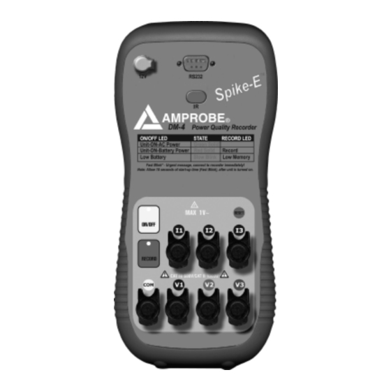
- Page 1 DM-4 Power Quality Recorder...
-
Page 2: Table Of Contents
DM-4 Power Quality Recorder TABLE OF CONTENTS 1. PRECAUTIONS AND SAFETY MEASURES................3 1.1 GENERAL........................3 1.2 PRELIMINARY INSTRUCTIONS ................3 1.3 DURING USE......................4 1.4 AFTER USE........................ 4 2.GENERAL DESCRIPTION ......................5 2.1 INTRODUCTION ......................5 2.2 FUNCTIONS....................... 5 3. - Page 3 DM-4 Power Quality Recorder 8. RECORDING IN PROCESS......................32 9. STOPPING A RECORDING......................33 9.1 STOP A RECORDING WITH THE REMOTE USER INTERFACE (PDA)....33 9.2 STOP A RECORDING WITH THE DOWNLOAD SUITE..........33 10. CONNECTING THE INSTRUMENT TO A PC................34 11. MEASURING PROCEDURES....................35 11.1 USING THE INSTRUMENT IN A SINGLE PHASE SYSTEM........35 11.2 USING THE INSTRUMENT IN A THREE PHASE 4- WIRE SYSTEM (WYE)..................36...
-
Page 4: Precautions And Safety Measures
DM-4 Power Quality Recorder 1. PRECAUTIONS AND SAFETY MEASURES 1.1 GENERAL For your own safety and to avoid damaging the instrument we suggest you follow the procedures hereby prescribed and to carefully read all the notes preceded by the symbol Before and during measurements please be very diligent in following instructions below: •... -
Page 5: During Use
DM-4 Power Quality Recorder • Please keep to the usual safety standards aimed at: Protecting against dangerous currents; Protecting the instrument against incorrect operations. • Only the accessories supplied with the instrument guarantee compliance with the safety standards. Accordingly, they must be in good condition and, if necessary, they must be replaced with identical models. -
Page 6: General Description
DM-4 Power Quality Recorder 2.GENERAL DESCRIPTION 2.1 INTRODUCTION The DM-4 also referred to as the Modular Data Logger (MDL), addresses the needs of the most demanding Power Quality professionals. The device incorporates full set of measuring features crucial for complete Power Quality analysis. An innovative Remote User Interface (PDA) allows safe, easy and convenient operation of the device remotely. -
Page 7: Preparing The Instrument
DM-4 Power Quality Recorder 3. PREPARING THE INSTRUMENT 3.1 INITIAL CHECK This instrument has been checked before shipment from an electrical and mechan- ical point of view. All possible precautions have been taken in order to deliver it in perfect condition. Notwithstanding, on receipt of the instrument we suggest that you check it summarily to make sure that no damage has occurred in transit. -
Page 8: Storage
DM-4 Power Quality Recorder 3.4 STORAGE For long time storage, please remove batteries to prevent leakage into the unit. Store unit in a safe location with room temperature conditions. To guarantee accurate measurements after a long storage period in severe environmental conditions, wait until the instrument resumes its normal conditions (see environmental conditions listed in paragraph 13.2). -
Page 9: Using The Dm-4 With The Remote User Interface (Pda)
DM-4 Power Quality Recorder 4.3 USING THE DM-4 WITH THE REMOTE USER INTERFACE (PDA) • Connect the Remote User Interface (PDA) to the DM-4 using the provided cable • Turn ON the DM-4 by pressing on the ON/OFF push button •... -
Page 10: Display Description Of The Remote User Interface
DM-4 Power Quality Recorder DISPLAY DESCRIPTION OF THE REMOTE USER INTERFACE (PDA) Download the Display real time information recorded files. of the monitored system. MDL-Main Menu View Real Time Data View the downloaded files. Allow the user to setup Setup a New Recording Session recording sessions with the Download Data desired configuration. - Page 11 DM-4 Power Quality Recorder • 1-Phase 2-wire, 60Hz System using 1000A clamp MDL-Main Menu View Real Time Data Setup a New Recording Session TM Setup Phase Selection: P 1 Ø 2 W (Y) Fund. Frequency: P 60 Hz Clamp Type: P 1000 Amps •...
- Page 12 DM-4 Power Quality Recorder In order to display the voltage waveform or harmonics for the monitored phase, click on Scope or Harm buttons. The waveform or the harmonics table for the monitored voltage phase will be displayed. P Voltage 1 Real Time Voltage Real Time Mode Harm 1...
- Page 13 DM-4 Power Quality Recorder How to Monitor Power Only? From the Voltage and Current screen menu, click on the Power button located at the bottom of the screen.The Real Time Power screen will appear as shown below with the following information: Real Power: P (kW); Reactive Power: Q (kVAR);...
-
Page 14: Setup A New Recording Session
DM-4 Power Quality Recorder 3-Phase 3-wire, 60HZ system with 1000A Clamp Because the 3Ø3W system doesn’t have a neutral wire, you need to follow the proper direction given in this manual to connect the DM-4 with the 3Ø3W electrical system you want to monitor. Refer to paragraph 11.3 •... -
Page 15: Set Date And Time For Automatic Recording Session
DM-4 Power Quality Recorder The MDL System setup allows you to configure the data logger device for the type of power system you want to perform the recording. • Phase Selection: 1Ø2W; 1Ø3W; 3Ø3W ( ); 3Ø4W ( Delta configuration Wye configuration •... -
Page 16: Main Menu
DM-4 Power Quality Recorder MDL System Setup MDL System Setup Phase Selection: P 3 Ø 4 W (Y) Phase Selection: P 3 Ø 4 W (Y) Fund. Frequency: P 60 Hz Fund. Frequency: P 60 Hz Clamp Type: P 1000 Amps Clamp Type: P 1000 Amps Integration Period: P 5 sec... -
Page 17: How To Set The Date And Time
DM-4 Power Quality Recorder 5.1.1 How to Set the Date and Time? When connecting to the data logger, if the date and time of the device are different from the Remote User Interface (PDA), the program will ask you if you would like to synchronize the data logger with the Remote User Interface (PDA). -
Page 18: How To Set The Type Of Electrical System Under Test
DM-4 Power Quality Recorder 5.2.1 How to Set the Type of Electrical System Under Test • Phase Selection This parameter permits you to select the type of electrical system under test among the following configurations: 1Ø2W: Single phase system 1Ø3W: Single phase system 3Ø3W: 3 wires system (three-phase system without neutral) 3Ø4W: 4 wires system (three-phase system with neutral) -
Page 19: Basic Setting: Recorder Config
DM-4 Power Quality Recorder 5.3 BASIC SETTING: RECORDER CONFIG This option allows you to check and eventually modify the recording parameters and the selected parameters (up to a maximum of 456). 5.3.1 MDL Parameter Setup This option allows you to setup the parameters for a recording session. When using the Remote User Interface (PDA) in basic setting, selecting any block will enable all the parameters under this block. -
Page 20: Advanced Setting: Recorder Configuration
DM-4 Power Quality Recorder 5.4 Advanced Setting: Recorder Configuration The advanced setting option allows you to setup the desired parameters you want for a recording session. To enter the advanced setting mode: 1) From the MDL main menu screen, click on MDL Main Menu and select Options MDL-Main Menu Click View Real Time Data... -
Page 21: Setting The Parameters Individually
DM-4 Power Quality Recorder 5.4.1 Setting the Parameters Individually To set-up the parameters individually for a recording session, select “Setup a New recording Session” from the MDL Main Menu. The MDL System Setup will appear. Click on Next to enter the MDL Parameter Setup screen. MDL-Main Menu MDL System Setup MDL Parameter Setup... -
Page 22: Setup The Parameters For Current
DM-4 Power Quality Recorder 5.4.4 Setup the Parameters for Current 1Ø2W Single Phase 1Ø3W Single Phase MDL Parameter Setup MDL Parameter Setup Voltage Current Power Voltage Current Power Variable Ø1 Variable Ø1 Ø2 Current Current Harmonics Harmonics Frequency Frequency Phase Shift Phase Shift Waveform Waveform... -
Page 23: Setup The Parameters For Voltage Harmonics
DM-4 Power Quality Recorder 3Ø3W Delta Configuration 3-phase 3Ø4W Wye Configuration 3-phase MDL Parameter Setup MDL Parameter Setup Voltage Current Power Voltage Current Power Variable Ø1 Ø2 Ø3 TOT Variable Ø1 Ø2 Ø3 TOT P (KWh) P (KWh) Q (kVARh) Q (kVARh) S(kVAh) S(kVAh) -
Page 24: Setup The Parameters For Current Harmonics
DM-4 Power Quality Recorder 2) From the MDL parameter setup screen, select voltage and choose “A” (harmonic) under the phase you want to monitor. You need to setup each phase separately when monitoring more than one phase. MDL Parameter Setup Harmonics Phase-1 Voltage Current Power Variable... -
Page 25: Download Data
DM-4 Power Quality Recorder 5.5 Download Data After a recording session, you can retrieve your data by downloading the file from the device to your PC, using the Download Suite, or from the device to your Remote User Interface (PDA). 5.5.1 Download Data with the Remote User Interface (PDA) To retrieve a file from the device with your Remote User Interface (PDA), click on Download Data from the MDL main menu. -
Page 26: View Downloaded Data
DM-4 Power Quality Recorder 5.5.2 View Downloaded Data This option allows you to view all downloaded files in the Remote User Interface (PDA). Once a file is downloaded, you can select it to be viewed. To view a down- loaded file, click on View Downloaded Data from the MDL main menu. The pro- gram will prompt you to the Saved Recordings screen. -
Page 27: Delete Session
DM-4 Power Quality Recorder 5.5.4 Delete Session To delete a recording session from the device, choose Delete Session from the main menu. The device will prompt you to the remote recording files. From the remote recording files screen, select a file or the files you want to delete and then click on Delete. - Page 28 DM-4 Power Quality Recorder Symbols Description Advised Settings ☺ ☺ Enable = the Instrument will record Voltage Sag, Surge, ANOM REC. and voltage spike Disable = the instrument will not record any voltage Sag, Surge, and voltage spike. ☺ ☺ V1, V2, V3 RMS value of the voltage of phase 1, phase 2, phase 3 V12, V23 or...
- Page 29 DM-4 Power Quality Recorder Symbols Description Advised Settings ☺ ☺ Qt, Q1, Q2, Q3, Values of the inductive reactive power (total, of phase 1, Q12, Q32, Q31 phase 2, phase 3) (only for 3 wires measurement) value of the reactive inductive power measured by the VAR Single phase: Q1 meters 1-2 and 3-2 respectively 3 wires: Qt...
-
Page 30: Reset
DM-4 Power Quality Recorder 5.5.5 RESET ( PRESS AND HOLD RESET KEY WHILE PRESSING ON RECORD This option re-establishes the default settings of the instrument. The default settings of the instrument consist of: ANALYZER CONFIG: Frequency: 60Hz Full scale of the clamps: 1000A Type of electrical system: 4 wires RECORDER CONFIG: Start: Manual (the recording is started at 00 sec mark on clock after pressing the RECORD key) -
Page 31: Recording Configuration
DM-4 Power Quality Recorder 6. RECORDING CONFIGURATION More practically, we may schematize the right procedure of use as follows: 1) Connect the External Power Supply 2) Check and eventually modify the basic settings of the instrument. 3) Select the parameters to be recorded. 4) Connect the DM-4 to the electrical system to be tested and push the ON/OFF button 5) Evaluate the values of the parameters under test... - Page 32 DM-4 Power Quality Recorder If during a recording the external power supply is de-energized, the instrument will continue the recording using the internal battery power until the batteries are exhausted (the data stored until the definitive turning off won’t get lost). For this reason we recommend that you ALWAYS insert a new set of batteries before a long recording.
-
Page 33: Recording In Process
DM-4 Power Quality Recorder 8. RECORDING IN PROCESS If during a recording the external power supply is de-energized, the instrument will continue the recording using the internal battery power until the batteries are exhausted (the data stored up to the point the instrument shuts down won’t get lost). -
Page 34: Stopping A Recording
DM-4 Power Quality Recorder 9. STOPPING A RECORDING The instrument uses a protective routine to avoid the risk of being disturbed or interrupted during a recording or an energy measurement. Once a recording has been started using automatic record mode, it won’t be sufficient to press the RECORD key on the device to stop the recording. -
Page 35: Connecting The Instrument To A Pc
DM-4 Power Quality Recorder 10. CONNECTING THE INSTRUMENT TO A PC In order to connect the instrument to a PC you must connect the serial cable shipped with the instrument to the serial output of the PC. The DM-IV serial cable has the following inner connections: Male connector 9 pins 3 3 Female connector 9 pins on the instrument side 5... -
Page 36: Measuring Procedures
DM-4 Power Quality Recorder 3) Install the software and start it – Close the introduction window 4) Press F2 and follow the commands. 5) Refer to software help file for further instructions. 11. MEASURING PROCEDURES 11.1 USING THE INSTRUMENT IN A SINGLE PHASE SYSTEM CAUTION The maximum voltage between L1 and COM inputs is CATIII 635V~ phase-phase and 370V~ phase –... -
Page 37: Using The Instrument In A Three Phase 4- Wire System (Wye)
DM-4 Power Quality Recorder 3) Turn ON the unit by pressing the ON/OFF push button 4) If you want to measure current and power, connect the clamp meter to the phase conductor respecting the specifications shown on the clamp and the connections shown in the picture. - Page 38 DM-4 Power Quality Recorder CAUTION If possible, before connecting the instrument to the electrical equipment to be tested take the power supply off the electrical equipment. 1) Check the cables connection. 2) Connect the phase and neutral voltage wires respecting the connections shown in the picture.
-
Page 39: Using The Instrument In A Three Phase 3- Wire System (Delta)
DM-4 Power Quality Recorder 11.3 USING THE INSTRUMENT IN A THREE PHASE 3- WIRE SYSTEM (DELTA) CAUTION The maximum voltage between V1, V2, V3 and COM (L2) inputs is CATIII 600V~ phase-phase. Do not measure voltages exceeding the limits prescribed by this manual. Should you exceed the voltage limits you could damage the instrument and/or its components or endanger your safety. - Page 40 DM-4 Power Quality Recorder 1) Check, and if needed modify, the basic settings of the instrument (see paragraphs 5.2 and 5.3). Particularly, the 3 wires mode must be set. 2) Connect the phase and neutral voltage wires respecting the connections shown in the picture.
-
Page 41: Maintenance
DM-4 Power Quality Recorder 12. MAINTENANCE 12.1 GENERAL The DM-4 is a precision instrument. For its’ use and storage, follow the recommendations and instructions contained in this manual in order to avoid possible damages. Never use the instrument in environments with a high humidity or temperature. Always turn off the instrument if it is not in use. -
Page 42: Technical Specifications
DM-4 Power Quality Recorder 13. TECHNICAL SPECIFICATIONS 13.1 FEATURES The accuracy is stated as [1% of the reading ± number of 2 digits]. It refers to the following atmospheric conditions: temperature 73°F± 2°F (23°C ± 1°C) with rela- tive humidity < 75%. 13.1.1 Voltage Measurement Range Accuracy... -
Page 43: Power Measurement (Cosθ: 0.5C - 0.5I)
DM-4 Power Quality Recorder 13.1.4 Power Measurement (cosΘ Θ : 0.5c – 0.5i) Value Ranges Accuracy Resolution 0 – 999.9W Active Power 1KW – 999.9KW 1MW – 999.9MW 0 – 999.9VAR Reactive Power 1KVAR – 999.9KVAR 1MVAR – 999.9MVAR 0 – 999.9VA ±(3%+2digit) Apparent Power 1KVA –... -
Page 44: Measurement Of Harmonics
DM-4 Power Quality Recorder 13.1.6 Measurement of Harmonics Voltage Range Accuracy Resolution DC – 25h ±(5.0%+2digit) 26h – 33h ±(10.0%+2digit) 0.1V 34h – 51h ±(15.0%+2digit) The voltage harmonics will be null under the following threshold: - DC: if <1V or <2% of 1 st harmonic - 1 st harmonic: if <2V - 2 nd - 51 st : if <1V or <2% 1 st harmonic Current... -
Page 45: General Characteristics
DM-4 Power Quality Recorder 13.1.9 General Characteristics Mechanical Features Dimensions: 8.9” (L) x 4.1” (La) x 2.1” (H) 225(L) x 104(La) x 54(H) mm Weight: 3.3 Lb (1.5kg) Internal Power Supply: 8 batteries 1.5V series AA Battery Life: 3-hours External Power Supply: Use only Amprobe power supply Adapter code DM4EXTPS Display: LED Sampling Speed: 83.33 usec at 60Hz. -
Page 46: Accessories
DM-4 Power Quality Recorder 13.3 ACCESSORIES 13.3.1 Standard Accessories The package contains: Replacement Parts Part Number Remote user interface (PDA) with Recommended Tungsten E2 Ordered connection cable through PALM retailers, visit www.palm.com Instrument DM-4 Carrying case HW1254A External power supply 12VDC DM-4EXTPS 1000A Clamp DM-CT-BKCE... -
Page 47: Appendix 1 - Recordable Parameters: Symbols
DM-4 Power Quality Recorder 14. APPENDIX 1 – RECORDABLE PARAMETERS: SYMBOLS Symbol Description V1, V2, V3 RMS value of the voltage of phase 1, phase 2, phase 3 respectively V12, V23 V31 Value of phase to phase voltages I1, I2, I3 RMS value of the current of phase 1, phase 2, phase 3 respectively RMS value of the current of the neutral Continuous component of voltage or current... -
Page 48: Appendix 2 - Theoretical Outlines
DM-4 Power Quality Recorder 15. APPENDIX 2 – THEORETICAL OUTLINES 15.1 VOLTAGE ANOMALIES (VOLTAGE SAG AND SURGE; SPIKE) The instrument records as voltage anomalies all those rms values, calculated every 11ms, beyond the percent thresholds of Voltage Reference (Vref) set during the pro- gramming. -
Page 49: Voltage And Current Harmonics
DM-4 Power Quality Recorder 15.2 VOLTAGE AND CURRENT HARMONICS 15.2.1 THEORY Any periodical non-sine wave can be represented as a sum of sinusoidal waves having each a frequency that corresponds to an entire multiple of the fundamental, according to the relation: ∞... -
Page 50: Limit Values For Harmonics
DM-4 Power Quality Recorder A fundamental element to detect the presence of harmonics is Thd defined as: This index takes all the harmonics into account. The higher it is, the more distorted the waveform gets. 15.2.2 Limit Values for Harmonics EN-50160 fixes the limits for the harmonic voltages, which can be introduced into the network by the power supplier. -
Page 51: Presence Of Harmonics: Causes
DM-4 Power Quality Recorder 15.2.3 Presence of Harmonics: Causes Any apparatus that alters the sine wave or uses only a part of such a wave caus- es distortions to the sine wave and therefore harmonics. All current signals are in some way distorted. -
Page 52: Power And Power Factor: Definitions
DM-4 Power Quality Recorder dangerous. Designers should take into consideration the three issues given below when designing a power distribution system that will contain harmonic current: • The neutral wire must be of sufficient gauge. • The distribution transformer must have an additional cooling system to continue operating at its rated capacity when not suited to the harmonics. - Page 53 DM-4 Power Quality Recorder In presence of distorted voltages and currents the previous relations vary as follows: ∞ Phase Active Power: ∑ cos(Θ Θ Where: (n=1,2,3) Phase Apparent Power: • I (n=1,2,3) = RMS value of kth Phase Reactive Power: √...
-
Page 54: Conventions On Powers And Power Factors
DM-4 Power Quality Recorder 15.3.1 Conventions on Powers and Power Factors As for the recognition of the type of reactive power, of the type of power factor and of the direction of the active power, the below conventions must be applied. The stated angles are those of phase-displacement of the current compared to the volt- age (for example, in the first panel the current is in advance from 0°... -
Page 55: Phase 3 Wire System
DM-4 Power Quality Recorder Value Significance The active power (positive or negative) is defined in the panel and therefore acquires the value of the active power in that moment. The reactive power (inductive or capacitive, positive or negative) is defined in the panel and therefore acquires the value of the reactive power in that moment. -
Page 56: Measuring Method: Outlines
DM-4 Power Quality Recorder 15.4 MEASURING METHOD: OUTLINES The instrument is able to measure: voltages, currents, active powers, inductive and capacitive reactive powers, apparent powers, inductive and capacitive power fac- tors, analog or impulse parameters. All these parameters are analyzed in a digital way: for each phase (voltage and current), 6 x 128 samples are acquired on a mod- ule of 16 x 20ms, repeated for the three phases. - Page 58 100795 Rev.B...
Need help?
Do you have a question about the AMPROBE DM-4 and is the answer not in the manual?
Questions and answers