Table of Contents
Advertisement
Quick Links
Advertisement
Table of Contents

Summary of Contents for AAS ULTRA ANALOG VA-3
- Page 1 USER MANUAL...
- Page 2 Information in this manual is subject to change without notice and does not represent a commitment on the part of Applied Acoustics Systems DVM Inc. The software described in this manual is furnished under a license agreement. The software may be used only in accordance of the terms of this license agreement. It is against the law to copy this software on any medium except as specifically allowed in the license agreement.
-
Page 3: Table Of Contents
1.3.3 Using Ultra Analog VA-3 as a Plug-in ....Getting Help ........10 About this Manual . - Page 4 CONTENTS 5 The Editor View 5.1 General Functioning of the Interface ......29 5.1.1 Knobs ........29 5.1.2 Switches .
-
Page 5: Contents
CONTENTS 5.4.6 Flanger ........58 5.4.7 Phaser . - Page 6 Sustain Pedal ....... . . 79 9 Using Ultra Analog VA-3 as a Plug-In Audio and MIDI Configuration .
-
Page 7: Introduction
Before discussing the synthesizer in more detail, we would like to take this opportunity to thank you for choosing an AAS product. We sincerely hope that this product will bring you inspiration, pleasure and fulfill your creative needs. -
Page 8: Installation And Authorization
Installation and authorization can therefore be carried out automatically in a single step and from a single file when your computer is online. AAS products use a copy protection system based on a a proprietary challenge/response key exchange and therefore their authorization does not rely on other third party software and/or hardware. -
Page 9: Exploring The Factory Sounds
Ultra Analog VA-3 as a plug-in. Note that in plug-in mode the audio and MIDI inputs, sampling rate, and buffer size are determined by the host sequencer. -
Page 10: Getting Help
AAS technical support representatives are on hand from Monday to Friday, 9am to 6pm EST. Whether you have a question on Ultra Analog VA-3, or need a hand getting it up and running as a plug-in in your favorite sequencer, we are here to help. Contact us by phone or email at:... -
Page 11: Architecture Of Ultra Analog
filtering lines are not totally independent since the output of the filter module from the first line can be sent to the input of the filter on the second line. Figure 1: General signal flow of Ultra Analog VA-3. This configuration is very flexible because, depending on the type of mixing applied, sources can be treated separately or in combination. -
Page 12: Multimbral Architecture
Architecture of Ultra Analog VA-3 2.2 Multimbral Architecture Ultra Analog VA-3 is a multitimbral synthesizer which can play two different timbres simultane- ously either in layered or split keyboard mode. The general architecture of the synthesizer is shown in Figure 2 and consists of a MIDI routing module, two independent Ultra Analog VA engines in parallel, a mixer, and a multi effects module. -
Page 13: The Home View
2.3 Interface Figure 3: The Utility section. 2.3.1 The Home View This is the main page for auditioning sounds and playing. The principal elements on this page are four controls allowing one to easily adjust high-level qualities or characteristics of the sound being played and modify it. -
Page 14: The Editor View
Clicking on the Editor button gives access to the synthesis engine itself. The multitimbral archi- tecture of Ultra Analog VA-3 includes two identical instances of the synthesis engine in parallel, each corresponding to one layer or sound. The graphical user interface of each synth engine is identical and has been organized around three different pages as shown in Figures 8, 9 and 10. - Page 15 2.3 Interface Figure 6: The Synth view. order to deselect this region. A layer can be switched on or off by clicking on the power switch icon located just before its label. Switching off a layer not only mutes its output but completely deactivates the synthesis engine of the layer.
- Page 16 Architecture of Ultra Analog VA-3 Figure 7: The layer mixer. The Modes View The lower section of this view includes a master clock, keyboard, unison, glide, vibrato and arpeg- giator modules which will be described in more details in Chapter 5. Just below is a clickable seven octave ribbon allowing one to play different notes on the range of the piano which can be useful when no MIDI keyboard is connected to the computer.
-
Page 17: The Settings View
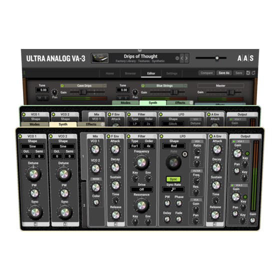
2.3 Interface Figure 9: The Synth view. Figure 10: The Effects view. 2.3.4 The Settings View The Settings page is accessed by clicking on the Settings button. This is where general parameters and options for, polyphony, tuning, MIDI assigments and MIDI configuration are adjusted. The different setting options will be described in details in Chapter 6. - Page 18 Architecture of Ultra Analog VA-3 Figure 11: The Settings view.
-
Page 19: The Home View
The Home View 3 The Home View This is the main page for auditioning sounds and playing. The principal elements on this page are four controls allowing one to easily adjust high-level qualities or characteristics of the sound being played and modify it. These knobs, labelled Modulation, Timbre, Envelope, and Effect, control macro parameters in each layer which are mapped to specific synthesis parameters affecting the same characteristic of the sound. - Page 20 The Home View in the Settings view and will be described in Chapter 7. The name of the assigned MIDI controller is displayed below each macro knob and it is set to None when there is no assignment. When an external controller is used to control a macro, an orange line is displayed around the corresponding knob in order to indicated the actual value associated with the knob.
-
Page 21: The Browser View
The Browser View 4 The Browser View In the context of Ultra Analog VA-3, a sound is a preset for the parameters of the entire synthesizer. Sounds are created by combining layers, each corresponding to a different instance of the synthesis engine. -
Page 22: The Sound Browser
When browsing by packs, the list of available packs is displayed in the left section of the browser as shown in Figure 14. Packs are divided into two categories, AAS packs and user packs. AAS packs comprise the new Ultra Analog VA-3 factory sounds, VA-2 legacy factory sounds, as well as any expansion pack which might be installed on the computer. - Page 23 4.3 The Sound Browser Figure 14: Browsing by sound pack. Figure 15: Browsing the entire library by sounds. then enters a name for the pack and clicks on the Create button. This creates an empty pack in the user pack list. Packs and the information corresponding to their sounds are stored as files in a Packs folder on your computer hard disk.
- Page 24 The Browser View Figure 16: Browsing the library by sound category. Figure 17: Browsing the library by creator. an Explorer window at the location where the files are stored while on Mac OSX, the command opens a Finder window. All the pack file names follow the same format which consists of the pack name followed by the VA-3 Pack extension.
-
Page 25: Managing Sounds
4.3 The Sound Browser Different commands can be applied to a user pack once it has been selected. These are revealed by clicking on the ellipsis icon located to the right of the pack name at the top of the browser. A pack can be renamed by choosing the Rename command. -
Page 26: Backing Up Of Sound Packs
This is only true however for sounds from user packs. AAS Packs can not be edited so drag and dropping sounds from these packs to a user pack is equivalent to a Copy command. -
Page 27: Importing Sounds From Previous Versions Of Ultra Analog Va
4.7 Importing Sounds from Previous versions of Ultra Analog VA Ultra Analog VA-3 includes a converter that allows one to import sounds from Ultra Analog VA-2. The conversion operation simply involves copying a Ultra Analog VA-2 pack file into the Ultra... - Page 28 Note that AAS expansion sound packs for Ultra Analog VA which were installed on your computer prior to the installation of Ultra Analog VA-3 should not be converted in this way. The Ultra Analog VA-3 installer you will have downloaded from our server should indeed also include your expansion sound packs and take care of their installation automatically.
-
Page 29: The Editor View
This section can be used as a reference for the controls appearing on the different modules of the synthesis engine of Ultra Analog VA-3. These modules are accessed from the Editor view which is displayed by clicking on the Editor button located at the top of the interface. -
Page 30: Synchronisation
The Editor View The Key modulation knobs are used to modulate a parameter depending on the note played on the keyboard. When in its center position, the value of the corresponding parameter is equal across the whole range of the keyboard. Turning the knob to the left increases the value of the parameter for low notes while decreasing its value for high notes. -
Page 31: The Modes View
5.2 The Modes View the list of available presets by scrolling up or down the list or using the arrows in the top right corner of the window. A preset is loaded once it is selected. It is possible to compare the new settings with the original ones by clicking on the Revert button in the right section of the window. -
Page 32: The Keyboard Module
The Editor View When using Ultra Analog VA-3 in plugin mode, the Tap Tempo pad is replaced by a Sync To Host switch. In its on position, the rate is synchronized with that of the host sequencer. When switched off, the tempo is determined by the value of the Rate knob. -
Page 33: The Macros Module
5.2 The Modes View Clicking on the Legato button switches the module into legato mode and the sliding between two notes then only occurs if the second note is played before the first one is released. When a note is played staccato, or in other words if a key is released before the next one is depressed, there is no glide effect. - Page 34 The Editor View small horizontal line when there is no assignment yet). This reveals a drop-down menu with a list of possible destination parameters. These range knobs are used to specify the amount of allowed modulation of the corresponding destination parameter. Their range varies between -100 % in their leftmost position and 100 % in their rightmost position with a value of 0 % when in their center position.
-
Page 35: The Vibrato Module
LFO to modulate the pitch signal of an oscillator. In Ultra Analog VA-3 , a dedicated module is provided for this effect. The Rate knob sets the frequency of the vibrato effect from 0.3 Hz to 10 Hz. The Amount knob sets the depth of the effect, or in other words the amplitude of the frequency variations. - Page 36 The Editor View Arpeggio Patterns The arpeggio pattern is set by the combination of the value of the Range, Span and Order controls. This module is switch on by clicking on the small LED located in the upper right corner of the module. The Range control is used to select the number of octaves across which the pattern is repeated.
-
Page 37: Ribbon
5.2 The Modes View note and a thirty-second note with binary and ternary beat division options. One can then fix the metric of the pattern by setting the loop point of the step display appropriately. Latch mode The Arpeggiator module is toggled in latch mode by clicking the Latch button to its on position. In this mode, the Arpeggiator keeps playing its pattern when the notes on the keyboard are released and until a new chord is played. -
Page 38: The Synth View
Ultra Analog VA-3 and therefore to customize its tone and behavior. The two oscillators of Ultra Analog VA-3 appear on the left of this view. They are followed by the two filter-amplifier lines and their associated mixers. One can switch from one line to the other by clicking on the tabs to the right of the oscillators. - Page 39 5.3 The Synth View Figure 20: Choice of wave forms provided by the Oscillator module. Pitch The pitch of the Oscillator module can be adjusted using the Octave, Semi and Detune controls. The Octave control allows one to transpose the pitch by octaves (upper or lower) while the Semi control is used to transpose the pitch by semitones.
-
Page 40: The Filter Module
Note that in sync mode, the sub-oscillator knob is not available. 5.3.2 The Filter Module Ultra Analog VA-3 is equipped with two multi-mode filters. The filters are patched in a flexible way in order to allow their use in parallel, in series or any combination of both. For even more flexibility, the cutoff frequency of the Filter 2 can also be locked to that of Filter 1. - Page 41 5.3 The Synth View Figure 21: Synchronization of the oscillator. The cutoff frequency and resonance of the filters can be modulated with different modulation sources. The Key knob allows one to adjust the amount of variation with the pitch signal from the keyboard while the Env knob is a gain control applied to the signal received from the Filter Env module.
- Page 42 The Editor View Figure 22: Frequency response of the low-pass filter. there is no emphasis around the cutoff frequency and the attenuation is -3dB at the cutoff frequency. The attenuation for frequencies located above the cutoff frequency depends on the order of the filter which is set by the Order menu, a slope of -12dB/Oct corresponding to a second order filter and a slope of -24dB/Oct to a fourth order filter.
- Page 43 5.3 The Synth View Band-Pass Filter Figure 24: Frequency response of the band-pass filter. The behavior of a band-pass filter is to let the frequencies in a band located around a center frequency and to attenuate the frequencies outside of this band as shown in Figure 24. The band- width of the band-pass filter is set with the Resonance knob while the center frequency is set with the Frequency knob.
- Page 44 The Editor View Figure 25: Frequency response of the notch filter. Figure 26: Frequency response of the formant filter. the parameters of these three filters (frequency, amplitude and Q-factor) one can cycle between all the vowels. The effect of the Frequency knob on the formant filter is to offset all the formants by the same factor and it is used to switch between male voice (left position), female voice (center) and child (right position).
- Page 45 5.3 The Synth View Filter Drive As seen in the preceding sections, some filters can boost the signal in some regions of the spectrum. Theoretically, with a high Q-factor the amplification can reach up to 50dB, but in real life, electronic components saturate before this level is reached and saturation is introduced in the signal.
-
Page 46: The Vca Module
The Editor View Note that the modulation entries on the Filter 2 module are kept active so do not forget to disable them in order to have the desired effect. Signal routing to the filters The filter mixers allow one to control how the signal from the different sources, the two oscillators and the noise source, are routed to the filters. -
Page 47: The Noise Generator Module
5.3 The Synth View The pan value can be modulated by signals from the LFO, the Amp Env modules and the pitch of the note played. The modulation signals moves the source relative to the source position determined by the settings of the Pan knob. Negative values of the modulation signal move the source to the left of the source while positive values move it toward the right. - Page 48 The Editor View Rate There are two ways to adjust the rate, or frequency, of the output of the LFO module. If the Sync switch is in its off position, the rate is fixed with the Rate knob. When the Sync switch is on, the frequency of the oscillator is fixed relative to the frequency (tempo) of the host sequencer or the master clock (see 5.2.1) in standalone mode.
-
Page 49: The Envelope Module
VCA module. 5.3.6 The Envelope Module Each row of Ultra Analog VA-3 is equipped with two envelope generators, the Filter Env and Amp Env modules which are used to modulate the Filter and Amp modules. Both envelope generators have the same user interface and offer the same functions. Envelopes are generated through the use of a standard ADSR (attack, decay, sustain, release) approach including MIDI velocity modulation and looping capabilities. - Page 50 The Editor View Figure 29: Response curve of an envelope generator. Broken line: exponential, full line: linear. The envelope modules generate a four segment envelope: attack, decay, sustain, release. The attack time is adjusted using the Attack knob. The attack time can also be modulated with the velocity signal received from the MIDI keyboard to make the attack time shorter as the velocity increases, the intensity of this effect being controlled using the Vel knob on the left of the Attack knob.
- Page 51 5.3 The Synth View behaves in exactly the same way as the Vel parameter associated with the Attack knob. Shape of the Envelope Segments We have so far determined the shape of the envelope by adjusting the duration of the different phases as well as their level.
-
Page 52: The Effects View
The Editor View Figure 30: Loop mode of an envelope generator. 5.4 The Effects View The Effects view is displayed by clicking on the Effects tabs in the layer mixer section and is based around a Multi-effects module. Note that there is a Multi-Effects module at the output of each layer and one at the output of the synthesizer after the layer mixer. -
Page 53: Equalizer
5.4 The Effects View 5.4.1 Equalizer The Equalizer module provides equalization over the low, mid, and high frequency bands. It is composed of a low shelf filter, two peak filters, and a high shelf filter in series, labelled LF, LMF, HMF, and HF respectively. -
Page 54: Compressor
The Editor View Q knob is used to adjust the so-called quality factor of the filter which controls the width of the frequency band on which the filter is active. In its leftmost position, the frequency band is wide and it gets narrower as the knob is turned clockwise. Figure 32: Peak filter. -
Page 55: Delay
5.4 The Effects View the threshold value and the portion of its input signal also exceeding the threshold value. As one might expect, increasing the ratio also increases the amount of compression applied to the signal. For example, a ratio of 1:5 means that if the input signal exceeds the threshold by 5 dB, the output signal will exceed the threshold by only 1 dB. -
Page 56: Distortion
The Editor View echo first from the left channel and then from the right channel and so on. In its rightmost position, the behavior will be similar but with the first echo coming from the right channel. These two extreme position correspond to the standard ping pong effect but a a less extreme behavior can be obtained by choosing an intermediate position. -
Page 57: Chorus
5.4 The Effects View 5.4.5 Chorus The chorus effect is used to make a source sound like many similar sources played in unison. It simulates the slight variations in timing and pitch of different performers executing the same part. The effect is obtained by mixing the original signal with delayed version obtained from the output of delay lines as shown in Figure 33. -
Page 58: Flanger
The Editor View the different voices in the stereo field. When in its leftmost position, there is an equal amount of left and right output signal on each channel. In other words the signal is the same on both channels. In its rightmost position, there is complete separation between the channels, the left output from the chorus is only sent to the left channel while the right output of the chorus is only sent to the right channel. - Page 59 5.4 The Effects View the delay, the lower is 0 and the smaller the spacing between the harmonics while decreasing the delay increases 0 and hence the distance between the harmonics. Figure 35: Frequency response of a Flanger module. Effect of the length of the delay line. The amount of effect is determined by the ratio of wet and dry signal mixed together as shown in Figure 36.
-
Page 60: Phaser
The Editor View Figure 37: Effect of the amount of feedback on the frequency response of a Flanger module. there is no modulation and the length of the delay line remains constant. As the knob is turned to the right, the length of the delay line starts to oscillate by an amount which increases as the knob is turned clockwise and at a frequency fixed with the Rate knob. - Page 61 5.4 The Effects View Figure 38: Phaser algorithm. of phase with that of the original signal. The amount of effect is determined by the ratio of wet and dry signal mixed together as shown in Figure 39. As the amount of wet signal sent to the output is reduced, the amount of rejection increases.
-
Page 62: Wah Wah
The Editor View Figure 39: Frequency response of a Phaser module. Effect of the mix between wet and dry signal on the frequency response. 5.4.8 Wah Wah The Multi-Effect module includes 2 different types of Wah effects: wah wah, and auto wah. These effects are used to enhance a frequency band around a varying center frequency using a bandpass filter. -
Page 63: Notch Filter
5.4 The Effects View Turning this knob clockwise increases the excursion of the center frequency. Note that the Depth parameter is also adjustable from the Play view. The Rate knob controls the frequency or rate of the modulation of the center frequency of the filter. - Page 64 The Editor View Figure 40: Frequency response of a notch filter. The amplifier section of this module is switched on or off by clicking on the LED located in the top right corner of the section labelled Amp on the left of the module. The Channel LED allows one to switch between the two channels of the amplifier.
-
Page 65: Tremolo
5.4 The Effects View The spring reverb is turned on or off by using the spring LED in the top right of the section labelled Spring. The Mix knob is used to set the amount of wet signal in the mix, turning the knob clockwise increasing the amount of reverberation in the signal. - Page 66 The Editor View distinguished anymore and can be assimilated to an exponentially decaying signal. The first part of the room response is called the early reflexion while the second is called the late reverberation. The total duration of the room response is called the reverberation time (RT). Figure 41: Impulse response of a room.
-
Page 67: Output Gain
5.4 The Effects View the source) depends strongly on the position of the listener. The farther we are from the sound source the quieter is the direct sound relatively to the room response. The ratio between the direct sound and the room response is adjusted with the Mix knob which in other words is used to adjust the perceived distance between the source and the listener. -
Page 68: The Settings View
The Voices control located at the top of the Settings window allows one to adjust the number of polyphony voices used by Ultra Analog VA-3. The number of voices is adjusted by clicking on the control and selecting the desired number of voices. In general, a higher number of voices is desirable but keep in mind that the CPU load is proportional to the number of voices used. -
Page 69: Microtonal Tuning
Tune controls in the layer mixer as will be discussed below. 6.1.3 Microtonal Tuning An interesting feature of Ultra Analog VA-3 is that it can be tuned according to different temper- aments using Scala micro-tuning files. Temperament files are loaded by clicking on the Tuning drop-down menu which shows a list of available temperament. -
Page 70: Keyboard
Ultra Analog VA-3 responds to MIDI program changes when the Enable Program Changes option of the MIDI Program setting is turned on. When this is the case Ultra Analog VA-3 will load, when it receives a MIDI program change message, the sound having the same index number, in the currently selected sound pack, as the program number in the message. -
Page 71: Control Change Assignments
8.2.2. 6.1.8 Control Change Assignments Any control on the Ultra Analog VA-3 interface can be manipulated by an external MIDI controller through MIDI control change assignments or MIDI links. In order to save the current configuration of assignments as the default map, use the Save Current as Default. This default map will be loaded the next time the program is started in standalone mode. -
Page 72: Utility Section And Layer Mixer
Utility Section and Layer Mixer 7 Utility Section and Layer Mixer The utility section is located at the top of the Ultra Analog VA-3 interface and it includes important parameters and monitoring tools. 7.1 Sound Display At the top of the utility section one finds the sound display with information on the currently loaded sound and its associated sound pack. -
Page 73: The Midi Led
MIDI signal. If the application is not receiving MIDI signal, make sure that the host sequencer is sending MIDI to Ultra Analog VA-3. If you are running in standalone mode, make sure that the MIDI controller you wish to use is well connected to your computer and that it is selected as explained in Chapter 8. -
Page 74: Level Meter
These can be layers which are used often in the creation of new sounds. By default, this list includes a list of AAS factory basic layers which can be used as init presets or a basis for new layers. The Save command is used to add new layers to this list of user saved presets. Note that layer presets can be renamed and deleted in the layer preset window. -
Page 75: The About Box
7.5 The About Box The optimal level for the signal lies in the light green zone of the level-meter (0 and +4 dBr) and should typically be reached when playing at mezzo forte (moderately loud) level. The 0 dB mark on the level meter has been adjusted to correspond to -20 dBFS (full scale). This means that at that level, the signal is -20 dB below the maximum allowed value. -
Page 76: Audio And Midi Settings
VA-3. Audio and MIDI configuration tools are accessed by clicking on the Audio Setup button located in the lower left corner of the Ultra Analog VA-3 interface and the MIDI button located just below the MIDI led in upper part of the interface. -
Page 77: Midi Configuration
The list of available MIDI inputs appears at the bottom of the Audio Setup dialog. Click on the Audio Setup button located in the lower left corner of the Ultra Analog VA-3 interface and then click on the checkbox corresponding to any of the inputs you wish to use. -
Page 78: Creating A Default Midi Assigment Map
Move a knob or slider on your MIDI controller (this can be a keyboard, a knob box, or any device that sends MIDI). This will link the control of the Ultra Analog VA-3 to the MIDI controller you just moved. -
Page 79: Modulation Wheel
8.2.7 Modulation Wheel Ultra Analog VA-3 responds to the signal from the modulation wheel of MIDI keyboards (contin- uous controller number 1). The first macro module is usually mapped to this controller. For more information on the Macros modules, please refer to section 5.2.5. -
Page 80: Using Ultra Analog Va-3 As A Plug-In
We review here some general points to keep in mind when using a plug-in version of Ultra Analog VA-3. 9.1 Audio and MIDI Configuration When Ultra Analog VA-3 is used as a plug-in, the audio and MIDI ports, sampling rate, buffer size, and audio format are determined by the host sequencer. 9.2 Automation Ultra Analog VA-3 supports automation functions of host sequencers. -
Page 81: Performance
9.6 Performance 9.6 Performance Using a plug-in in a host sequencer requires CPU processing for both applications. The load on the CPU is even higher when multiple instances of a plug-in or numerous different plug-ins are used. To decrease CPU usage, remember that you can use the freeze or bounce to track functions of the host sequencer in order to render to audio the part played by a plug-in instead of recalculating it every time it is played. -
Page 82: License Agreement
“applets” incorporated into the Software. AAS retains ownership of and title to all intellectual property rights in the Software, underlying technology, related written materials, logos, names and other support materials furnished either with the Software or as a result of this Agreement, including but not limited to trade secrets, patents, trademarks and copyrights therein. - Page 83 Licensee, if any, subject to any changes to this License made by AAS from time to time and provided to the Licensee, provided AAS is under a separate obligation to provide to Licensee such updates or upgrades and Licensee continues to have a valid license which is in effect at the time of receipt of each such update or new release.
- Page 84 Agreement shall constitute a waiver or consent unless expressly waived or consented to in writing by a duly authorized representative of AAS. A waiver of any event does not apply to any other event, even if in relation to the same subject-matter.
- Page 85 Index about, 75 drop-down menus, 29 adsr, 49 editor, 29 amplifier, 46 effect, 13, 19, 33 architecture, 11, 12 effects arpeggiator, 35 master clock, 31 latch, 37 synchronization, 30 looping, 36 effects view, 16, 52 pattern, 36 output gain, 67 rate, 36 studio mix, 67 rhythmic pattern, 36...
- Page 86 INDEX frequency, 68 phase, 48 rate, 48 glide, 32 reset mode, 48 guitar amplifier, 16, 63 synchronization, 30 wave shape, 47 hard synchronization, 40 limiter, 74 help, 8, 10 low-pass filter, 40, 41 high-pass filter, 40, 42 home, 13, 19 macro, 13, 19, 33 home view, 19 macro:effect, 33...
- Page 87 INDEX load, 30 pack, 21, 22 paste, 30 AAS, 21 presets, 30 backup, 22, 26 save, 30 commands, 22 modules, 29 create, 22 multi-effect, 16, 52 creating, 22 auto wah, 62 delete, 22 cabinet, 63 duplicate, 22 exchange, 22 chorus, 57...
- Page 88 INDEX reverb, 16, 65 user, 22 ribbon, 16, 37 sound browser, 22 speaker, 63 sampling rate, 7, 9 split keyboard, 37 saturation curve, 45 spring reverb, 63 save, 21, 22 square, 38 save as, 21, 22 standalone, 8 saw-tooth, 38 start-up, 8 scala files, 69 studio mix, 67...
Need help?
Do you have a question about the ULTRA ANALOG VA-3 and is the answer not in the manual?
Questions and answers