Table of Contents

Related Manuals for tornos MULTIDECO 26/6


Summary of Contents for tornos MULTIDECO 26/6
- Page 1 INSTALLATION DECO 26/6 ULTI DECO 32/6i ULTI 300381 en ∆ ATTENTION ! TORNOS SA Before handling / operating the machine, Printed in Switzerland CH–2740 MOUTIER read first the SAFETY REGULATIONS ! Copyright (c)1999–2002 http://www.tornos.ch...
- Page 2 TORNOS S.A. cover all details of the hardware and software or to anticipate every con- tingency.
-
Page 3: Table Of Contents
............INSTALLATION OF AN IEMCA BARFEEDER FOR MULTIDECO 26/6 . - Page 4 ..........ELECTRIC INSTALLATION MULTIDECO 26/6 .
-
Page 5: General
Note: Width 1600 mm 1720 mm Placed on the right side of the machine, this plate indicates primarily the machine version number, to be quoted when contacting TORNOS ser- Height (without indicator lamp) 1950 mm 2158 mm vices. Weight of machine equipped with... -
Page 6: Installation Of An Iemca Barfeeder For Multideco
These specifications must be strictly complied with to avoid malfunction- ing of the bar feeding system, which might be imputed to the lathe. TORNOS declines any liability whatsoever, should a damage or acci- dent be imputed to a tube / feeder which do not conform to the said specifications &/or standards in force. - Page 7 INSTALLATION – M DECO 26/6 – M DECO 32/6i ULTI ULTI >>> 300381 en – 06/02 Chap. 1.4 /3...
-
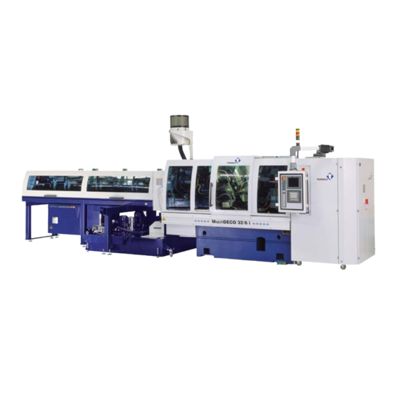
Page 8: Presentation Multideco 26/6
INSTALLATION – M DECO 26/6 – M DECO 32/6i ULTI ULTI PRESENTATION M DECO 26/6 ULTI See–thru door for machining range Ident. no. 217439 See–thru door for chuck and feed range Ident. no. 217441 See–thru door for spindle housing Ident. no. 217440 See–thru door for manual chucking range Ident. -
Page 9: Presentation Multideco 32/6I
INSTALLATION – M DECO 26/6 – M DECO 32/6i ULTI ULTI PRESENTATION M DECO 32/6i ULTI See–thru door for machining range Ident. no. 217439 See–thru door for chuck and feed range Ident. no. 217441 See–thru door for spindle housing Ident. no. 217440 See–thru door for manual chucking range Ident. - Page 10 INSTALLATION – M DECO 26/6 – M DECO 32/6i ULTI ULTI >>> 300381 en – 06/02 Chap. 1.6 /6...
-
Page 11: Unpacking And Cleaning
ULTI ULTI appropriate equipment supplied with the machine, which must be be returned to TORNOS S.A. after use. located only in the places indicated in transport documents 300379 or 300369. Replace the coolant tank, the conveyor, the MAYFRAN tank, reconnect the tubes. -
Page 12: Unpacking
INSTALLATION – M DECO 26/6 – M DECO 32/6i ULTI ULTI UNPACKING CLEANING Pull out nails from the cover and then from the walls of the case. Remove the 2.3.1 Removal of rust–proofing vacuum–packing plastic. ⇒ Note: Remove the wooden wedges and ropes that hold various items. The rust inhibitor applied depends on the particular destination. -
Page 13: Location/Installation
INSTALLATION – M DECO 26/6 – M DECO 32/6i ULTI ULTI LOCATION/INSTALLATION >>> FLOOR PLAN ⇒ Note: The dimensions relate to the standard configuration with optional (addi- tional) tank and cooler. Be sure to take into account for your particular floor plan the dimensions of other options added to the machine, such as barfeeder, mist &... -
Page 14: Floor Plan Multideco 26/6
INSTALLATION – M DECO 26/6 – M DECO 32/6i ULTI ULTI 3.1.1 Floor Plan M DECO 26/6 ULTI 199260f1 (dimensions with MSF–832 barfeeders for 4 metre bars) 300381 en – 06/02 Chap. 3.1.1 /2... -
Page 15: Floor Plan Msf-832 On Multideco
INSTALLATION – M DECO 26/6 – M DECO 32/6i ULTI ULTI 3.1.2 Floor Plan MSF–832 on M DECO 26/6 ULTI (9300) 199413 (dimensions with MSF–832 for 4 metre bars) 300381 en – 06/02 Chap. 3.1.2 /3... -
Page 16: Floor Plan Multideco 32/6I
INSTALLATION – M DECO 26/6 – M DECO 32/6i ULTI ULTI 3.1.3 Floor Plan M DECO 32/6i ULTI 199264f1 (dimensions with MSF–832 barfeeders for 4 metre bars) 300381 en – 06/02 Chap. 3.1.3 /4... -
Page 17: Installation
INSTALLATION – M DECO 26/6 – M DECO 32/6i ULTI ULTI INSTALLATION 3.2.2 Levelling 3.2.1 Surface load ∆ Caution! ∆ To ensure correct functioning of the machine under the best possible Caution! conditions, the levelling procedure described hereafter must be strictly Take account of the admissible loading of the floor depending on the complied with. - Page 18 INSTALLATION – M DECO 26/6 – M DECO 32/6i ULTI ULTI ∆ Caution! Once the machine is in position, remove the foam rubber protection 6 from the machine base near the coolant tank. (Figs. 301 & 302) Positioning of the level (217147) 5 (2x 240950) 1.
- Page 19 INSTALLATION – M DECO 26/6 – M DECO 32/6i ULTI ULTI 3. Place the level parallel to the longitudinal axis of the machine (Fig. 304) 2. With the level in diagonal position (Fig. 303), effect horizontal levelling by and if necessary adjust the setting by means of levelling element no. 1. means of levelling element nos.
-
Page 20: Removing Transport Locks
INSTALLATION – M DECO 26/6 – M DECO 32/6i ULTI ULTI 3.2.3 Removing transport locks Action Notes Remove the wooden wedges and Oil tank, chip pan, manipulator, ropes that hold various items in hatches. place. Remove mechanical locking Locking device devices Put away the locking pieces for possible future use. -
Page 21: Moving The Machine
INSTALLATION – M DECO 26/6 – M DECO 32/6i ULTI ULTI MOVING THE MACHINE >>> If the machine has subsequently to be moved (for example in the event of a move to different premises), ensure that the conditions and means of trans- port comply with transport document 300369 supplied with all the machine documentation. -
Page 22: Electric Installation Multideco 26/6
INSTALLATION – M DECO 26/6 – M DECO 32/6i ULTI ULTI ELECTRIC INSTALLATION M DECO 26/6 ULTI XS38 socket for XT0 input chip conveyor terminal box Barfeeder XS 94 QS0 main switch Additional tank XS78 Fig. 306 XS2 socket for coolant motor TC1 transformer see Figs. - Page 23 INSTALLATION – M DECO 26/6 – M DECO 32/6i ULTI ULTI Transformer Autotransformer Fig. 308 Fig. 309 XT10 Bridging if no terminal box autotransformer 300381 en – 06/02 Chap. 3.4 /11...
-
Page 24: Installation Characteristics
INSTALLATION – M DECO 26/6 – M DECO 32/6i ULTI ULTI 3.4.1 Installation characteristics XT0 input terminal box ∆ Danger ! For connecting and any other work on the electric equipment, the power must be cut off. The work must be carried out only by an author- ized technician to avoid the danger of electrocution. -
Page 25: Electric Connection To 200V - 240Vac Mains
INSTALLATION – M DECO 26/6 – M DECO 32/6i ULTI ULTI 3.4.2 Electric Connection to 200V – 240VAC Mains Switch off general electrical installation supply Mains 200V to 240VAC 50Hz/60Hz Connect general electrical installation supply to machine Section acc. to ASE 70mm or acc. - Page 26 INSTALLATION – M DECO 26/6 – M DECO 32/6i ULTI ULTI Switch on main machine switch QS0, see Fig. 306 Check XS18 service socket voltage see Fig. 306 220V–240V or XS17 US–socket voltage 100V–110V – Turn off Main Switch QS0. –...
-
Page 27: Electric Connection To 380V - 480Vac Mains
INSTALLATION – M DECO 26/6 – M DECO 32/6i ULTI ULTI 3.4.3 Electric Connection to 380V – 480VAC Mains Switch off general electrical installation supply Mains 380V to 420VAC / 50Hz 440V to 480VAC / 60Hz Connect general electrical installation supply to machine Section acc. - Page 28 INSTALLATION – M DECO 26/6 – M DECO 32/6i ULTI ULTI Switch on main machine switch QS0, see Fig. 306 Check XS18 service socket voltage see Fig. 306 220V–240V or XS17 US– socket 100V–110V – Turn off main switch QS0 –...
-
Page 29: Electric Connection To 500Vac Mains
INSTALLATION – M DECO 26/6 – M DECO 32/6i ULTI ULTI 3.4.4 Electric connection to 500VAC mains Switch off general electrical installation supply Mains 500VAC 50Hz / 60Hz Connect general electrical installation supply to machine Section acc. to ASE 35mm or acc. -
Page 30: Connection Of Various Machine Peripherals
INSTALLATION – M DECO 26/6 – M DECO 32/6i ULTI ULTI Switch on main machine switch QS0, see Fig. 306 Check XS18 service socket voltage, see Fig. 306 220V–240V or XS17 US–socket voltage 100V–110V – Turn off main switch QS0 –... -
Page 31: Electric Installation Multideco 32/6I
INSTALLATION – M DECO 26/6 – M DECO 32/6i ULTI ULTI ELECTRIC INSTALLATION M DECO 32/6i ULTI XT0 input terminal box QS0 main XS18 switch TC1 transformer, RS232 Socket see Fig. 314 Fig. 311 Fig. 312 300381 en – 06/02 Chap. -
Page 32: Installation Characteristics
INSTALLATION – M DECO 26/6 – M DECO 32/6i ULTI ULTI 3.5.1 Installation characteristics Power socket, MAYFRAN chip GENERAL CHARACTERISTICS conveyor XS79 Components Description Characteristics Machine power Average power output: approximately 60 kW (depending on machine usage) Installed power: approximately 80 kVA XS38 socket for Supply Nominal voltage toler-... - Page 33 INSTALLATION – M DECO 26/6 – M DECO 32/6i ULTI ULTI TC1 Transformer XT10 input terminal box Fig. 314 Autotransformer Terminal box XT10 positioning Fig. 315 300381 en – 06/02 Chap. 3.5.2 /21...
-
Page 34: Connection And Inspection Procedure
INSTALLATION – M DECO 26/6 – M DECO 32/6i ULTI ULTI 3.5.3 Connection and inspection procedure Switch off general electrical installation supply Mains 380V to 420V/50Hz or See table below 440V to 460V/60Hz? Connect general electrical Section acc. to ASE recommendation 50 mm installation supply to to local regulations machine... -
Page 35: Electrical Connection Depending On Mains Type
INSTALLATION – M DECO 26/6 – M DECO 32/6i ULTI ULTI 3.5.4 Electrical connection depending on mains type Utility networks Autotransformer TM2 Machine requiring an autotransformer Three–phase voltages Frequencies Section Inlet terminal strip 2 mm 3L – PE 50Hz 60Hz 3 x 50 mm Inlet/outlet terminal strip R 200V... -
Page 36: Pneumatics Installation
INSTALLATION – M DECO 26/6 – M DECO 32/6i ULTI ULTI >>> PNEUMATICS INSTALLATION 3.6.1 Required air quality ∆ ∆ Caution! – The machine must be supplied with dry, oil–free air. – If the air in the connected network contains oil or condensate, it is necessary to install an air drier at the inlet to the circuit in order to prevent incorrect functioning or machine breakdown. - Page 37 INSTALLATION – M DECO 26/6 – M DECO 32/6i ULTI ULTI Pneumatic Compressed air distribution 1 supply Pneumatic distribution 2 300381 en – 06/02 Chap. 3.6.1 /25...
- Page 38 INSTALLATION – M DECO 26/6 – M DECO 32/6i ULTI ULTI >>> 300381 en – 06/02 Chap. 3.6.1 /26...
Need help?
Do you have a question about the MULTIDECO 26/6 and is the answer not in the manual?
Questions and answers