Table of Contents
Advertisement
Advertisement
Table of Contents
Troubleshooting

Related Manuals for Carlson BRx7


Summary of Contents for Carlson BRx7
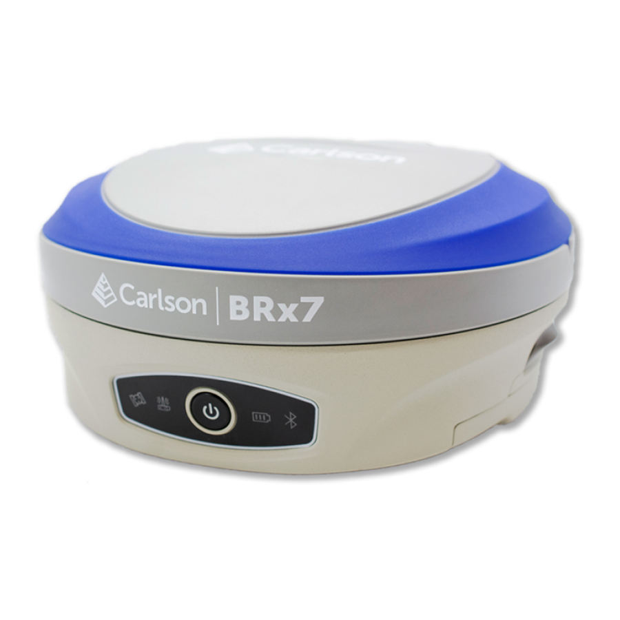
- Page 1 www.carlsonsw.com USER MANUAL Revision: A2 August 25 , 2020 v2...
- Page 2 HOWEVER ARISING, FOR ANY INACCURA- the patent rights of Carlson Software. CIES IN THIS DOCUMENT. Trade marks CARLSON and the symbol used in the CARLSON logo are registered trade marks of Carlson Software in the United States and other countries. apply innovation...
-
Page 3: Table Of Contents
Installing/Connecting the BRx7 ..............15 Installing UHF Antennas .................18 Installing the BRx7 on a Tribrach ..............18 Installing the BRx7 on a Range Pole ...............19 Connecting to a Power Source ...............20 Connecting to an External Device ..............21 Powering the BRx7 On/Off ................22 Inserting and Removing the MicroSD Card/SIM Card ........23... - Page 4 Firmware Update ...................51 How to Download Static Data ................54 Appendix A: Troubleshooting .................55 Overview ......................55 Troubleshooting .....................56 Appendix B: Technical Specifications ...............59 Overview ......................59 Technical Specifications ..................60 Appendix C: Radio Mode/QR Code ..............65 Overview ......................65 Radio Mode ....................66 QR Code ......................
-
Page 5: Chapter 1: Introduction
Chapter 1: Introduction Overview Introduction This User Guide provides information to help you quickly set up your BRx7 GNSS Smart Antenna. You can download this manual from the Carlson website at www.carlsonsw.com. Topic Page Contents Product Overview Key Features What’s Included in Your Kit... -
Page 6: Product Overview
With multiple wireless communications ports and an open GNSS interface, the BRx7 can be used in a variety of operating modes. Use the BRx7 as a precise base station for sending RTK to your existing rover network. Turn BRx7 into a lightweight and easy‐to‐use rover by connecting it to your base via UHF radio or cellular network. - Page 7 Product Overview Product Overview The BRx7 receiver is powered by the Athena RTK technology. The BRx7 provides state‐of‐the‐art RTK performance when receiving corrections from a static base station or network RTK correction system. With multiple connectivity options, the BRx7 allows for RTK corrections to be received over radio, cell modem, Wi‐Fi, Bluetooth, or serial connection.
- Page 8 Atlas‐capable devices to adjust accordingly, providing excellent convergence performance. WARNING Your BRx7 is equipped with a UHF radio. If you choose to use the radio, you may need to obtain a license. | Page...
- Page 9 Product Overview aRTK Position aRTK is an innovative feature available in Carlson’s BRx7 Smart Antenna that greatly mitigates the impact of land‐based communication instability. Aiding Powered by Hemisphere’s Atlas L‐band system service, aRTK provides an additional layer of communication redundancy to RTK users, assuring that productivity is not impacted by intermittent data connectivity.
-
Page 10: Key Features
Key Features Key features The key features of the BRx7 Smart Antenna include: • Multi‐frequency GPS, GLONASS, BeiDou, Galileo, QZSS, IRNSS, and Atlas Lband • Long‐range RTK baselines up to 50 km with fast acquisition times • UHF (400 MHz & 900 MHz), cellular, Bluetooth, and Wi‐Fi wireless communication •... -
Page 11: What's Included In Your Kit
What’s Included in Your Kit What’s included As shown in Table 1‐1 below, the BRx7 is available in a variety of kits, with supplementary products sold as “controller/option kits”, “accessory kits” or in your kit simply as separate accessories. Contents can change without prior notice. - Page 12 | Page...
-
Page 13: Chapter 2: Installation
Chapter 2: Installation Overview Introduction Chapter 2 provides instruction on how to install your BRx7 Smart Antenna. Topic Page Contents Ports and Connections Installing/Connecting the BRx7 Installing UHF Antennas Installing the BRx7 on a Tribrach Installing the BRx7 on a Range Pole... -
Page 14: Ports And Connections
Audio Speaker UHF Antenna Connector 7‐pin Diagnostic Port 5‐pin Power/Data Port 5/8” Mounting hole Figure 2‐1: BRx7 ports and connectors Table 2‐1: BRx7 ports and connections Main Kits What to connect 7‐pin Diagnostic Port (LEMO) Diagnostic cable for serial or USB 5‐pin Power/Data Port (LEMO) -
Page 15: Installing/Connecting The Brx7
Installing/Connecting the BRx7 Installing The BRx7 comes standard with two long‐life lithium batteries (see What’s Included in Your Kit) providing up to 12 hours of operation. The batteries batteries are hot‐swappable and may be changed while your work. To install the battery, slide each latch so that the lock is showing. - Page 16 Installing/Connecting the BRx7 Installing Press the button on the side to open the battery compartment and remove the door as shown in Figure 2‐3. batteries Figure 2‐3: Battery compartment door removed Installing Place the battery into the compartment. Take care to ensure the contacts on the battery are on the same side as the contacts on the receiver.
- Page 17 Installing/Connecting the BRx7 Installing To close the door cover, ensure the tab is unlocked. Slide the latch to cover the lock and lock the door (Figure 2‐5). batteries Figure 2‐5: Closed and locked battery compartment door Page |...
-
Page 18: Installing Uhf Antennas
Installing UHF Antennas Installing UHF To install the external UHF antenna of the BRx7, locate the UHF antenna Antennas (8030.042.007) from the kit list under What’s Included in Your Kit. Insert the connector end of the UHF antenna and rotate clockwise to secure the antenna to the BRx7. -
Page 19: Installing The Brx7 On A Range Pole
Installing the BRx7 on a Range Pole Installing the Use the standard 5/8‐11” mount on the bottom of the BRx7 to secure the BRx7 on a unit to a field standard 5/8‐11” range pole. range pole The BRx7 should be placed carefully on the range pole to ensure cross‐... -
Page 20: Connecting To A Power Source
Connecting to a Power Source Connecting to a The BRx7 has two main power sources. The first power source is the power source internal removable battery described in the earlier portion of this chapter. The second power source is the external power cable (Part Number 8030.064.027). -
Page 21: Connecting To An External Device
Figure 2‐9: 7‐pin diagnostic connector To download your data files, connect the 7‐pin Lemo connector end of the cable to the BRx7. Plug the USB end into a computer. You can access the internal memory of the receiver via the filesystem. -
Page 22: Powering The Brx7 On/Off
Powering the BRx7 On/Off Powering the To power on the BRx7 receiver, press the I key for one second, and wait for BRx7 On/Off the device to beep three times and power on. To power off the BRx7 receiver, press the I key until the receiver beeps and the LED lights blink. -
Page 23: Inserting And Removing The Microsd Card/Sim Card
Caution: Use electrostatic discharge (ESD) protection, such as wearing an ESD strap that is attached to an earth ground before inserting or removing the SIM card on the BRx7. If an ESD strap is not available, then touch a metal object prior to accessing the SIM card holder. - Page 24 | Page...
-
Page 25: Chapter 3: Setup And Configuration
Overview Introduction Chapter 3 contains the information you need to set up and configure your BRx7 Smart Antenna. Contents Topic Page Control Panel Overview Setting up the BRx7 Bluetooth Communication WebUI Firmware Update How to Download Static Data Page |... -
Page 26: Control Panel Overview
Control Panel Overview Control Panel Refer to the table below for information on the control panel LED overview indicators. Table 3‐1: LED lndicators Icon Colors Description Satellite Not receiving satellites Green Flashing Red Receiving satellites but no solution Flashing Green Has a solution but is not fixed Green Fixed Alternate Red... -
Page 27: Setting Up The Brx7
Setting up the BRx7 Setting up the Figure 3‐1 shows a typical setup for a base station (tripod is not included). BRx7 The antenna is connected to the bottom of the unit; you have the option of attaching the antenna to the antenna bracket to face the antenna upward. -
Page 28: Bluetooth Communication
Bluetooth‐enabled device, such as a data collector, you can Communication wirelessly communicate with the BRx7. When you attempt to connect the BRx7 to a Bluetooth‐enabled device, such as a hand‐held data collector, the following BRx7 Bluetooth information appears on the device: xxxxxxxxxxxxxx, e.g. -
Page 29: Carlson Webui
Once connected to your device, type or copy the following IP address into your URL bar: http:/ /192.168.10.1/ The WebUI will prompt you for a username and password. The default username and password are: • Username: admin • Password: brx7 Page |... - Page 30 WebUI (continued) Status tab The Status tab provides general GNSS information including System Mode, Latitude, Longitude, and Height. lnformation tab The lnformation tab contains device and module information and current software and firmware versions. Download tab The Download tab allows you to log and review multiple data files from the on‐board memory of the device.
- Page 31 BRx7. The Atlas expiration date will be displayed under this field. ln addition, the ability to update the BRx7 with new subscriptions is available under the AuthCode field. Type the new Atlas code and the device will automatically update.
- Page 32 Self‐Test provides an application review to ensure the device functioning properly. Restore Factory Settings returns the BRx7 to all default settings and performs a full power cycle. Reset initiates a complete device shut down, creating a hard reset to the device and stopping any application activity.
- Page 33 (continued) Working Mode When using a UHF datalink, channel tables must be configured by a certified Carlson dealer, or by uploading a channel table file provided by a dealer. lmportant: The Advanced UHF Settings can only be accessed by Carlson or certified Carlson dealers.
- Page 34 WebUI (continued) Working Mode Reference the following table for Working Mode fields and descriptions: (continued) Field Description Cutoff Angle Satellites at a lower angle to the horizon than “5” are not used in the GNSS solution. GLONASS Enable or disable the use of GLONASS satellites.
- Page 35 (continued) Working Mode System Mode (continued) The BRX7 can be configured as a survey rover, base station, or run a static observation. To set the base location select one of the following positions: • Single Position: Upon startup, the BRx7 will average its position and use that position for the base position.
- Page 36 (continued) Working Mode Data Link (continued) The BRx7 supports the sending and receiving of RTK via the internal UHF radio, external devices (such as an external radio) via serial, TCP/IP, NTRIP, and Bluetooth (rover only). Internal UHF Your BRx7 comes without a channel table loaded. Only Carlson or a Carlson certified dealer can create the file to upload a channel table.
- Page 37 The frequency, bandwidth, and transmit power (base only) is shown next to the channel. Radio Mode: The BRx7 supports PacCrest protocols (GMSK and 4FSK modulation), Satel protocols, and Trimtalk protocols. For a full list of protocols, with descriptions (FEC, Scrambling, over the air link rate, and modulation), please refer to Appendix C.
- Page 38 BRx7 Power Cable - n/a - Power cable only Network The BRx7 supports TCP/IP connections for a direct connection between base and rovers via cellular as well as NTRIP. NTRIP NTRIP requires a specific IP address, username, and password. When used as a base, the BRx7 is an NTRIP server.
- Page 39 NTRIP for a Rover, click Get Mountpoint to generate a list of available mountpoints. WARNING: lf the BRx7 has not yet established an internet connection via the Internal GSM modem, the Get Mountpoint button will not operate. You can configure the APN settings while using TCP/IP so that an internet connection is established.
- Page 40 WebUI (continued) Working Mode Some networks require a GNSS position prior to sending RTK. To send GNSS positions to the network, click on the dropdown menu next to Upload GGA (continued) and select a rate. After establishing an internet connection, change Connect Mode back to NTRIP and proceed with the configuration.
- Page 41 TCP Server and type in a Port name. The TCP Server requires that the SIM card provide a public IP address. The public IP address can be found in the lnformation tab on the BRx7 WebUI. Note: The Auto Connect identifies that the receiver connects to the network when powered up.
- Page 42 WebUI (continued) Working Mode lf the BRx7 is running as a rover, select TCP Client and type in the IP address and Port of the base. (continued) Note: The IP address and Port of the base is under the lnformation tab of the base station.
- Page 43 WebUI (continued) Working Mode Rover/Bluetooth (continued) The Rover/Bluetooth is typically used with third‐party software when streaming network corrections to the data collector internet and then sending them to the BRx7 via the Bluetooth communication port. Page |...
- Page 44 WebUI (continued) Working Mode Static (continued) Use Static mode to take a static observation of a point and stop logging (for both base and rover) if the position moves. Select Static next to System Mode and configure the log file. To configure a file, refer to Working Mode for instructions.
- Page 45 The BRx7 will audibly indicate when the receiver is in Base or Rover mode. Voice indication covers logging data and declaring when the BRx7 has achieved RTK float and RTK fix. This is important when working in a low visibility environment.
- Page 46 WebUI (continued) Device Sensor Configuration Turn on the Sensor, using the drop‐drown arrow to select the desired rate. (continued) | Page...
- Page 47 WebUI (continued) NMEA Message To enable NMEA messages, click the NMEA & Athena Log tab. Adjust the NMEA messages that are output over the 5‐pin serial port and over Bluetooth. Page |...
- Page 48 WebUI (continued) NMEA Message Refer to Table 3‐3 for NMEA Message fields and descriptions: (continued) Table 3‐3: NMEA Message Fields and Descriptions Field Description NMEA Log Stare the NMEA or binary messages that are turned on to the internal memory of the receiver or to an SD Card.
- Page 49 While the receiver is logging data, the WebUI will display [Recording] next to System Mode under the Status tab. To stop recording, click Stop Record. (continued) To download the log, click the Download tab. All logs stored on the BRx7 internal hard drive will display. Page |...
- Page 50 WebUI (continued) NMEA Message Click Delete to delete the log. (continued) Multiple logs can be downloaded or deleted at one time by selecting the box next to each of the logs and clicking Package or Delete Selected. Satellites lf you wish to exclude a specific satellite, select the Don’t track checkbox next to that satellite in the list.
-
Page 51: Firmware Update
Firmware via WebUI Using the Management tab under the WebUI, select the Choose File but- ton to find the appropriate firmware of application software for the BRx7 device. After selecting the correct firmware/software file, click the green Upload File button. - Page 52 Firmware Update (continued) Updating A status bar indicates the level of progress for the updating firmware / Firmware via software. WebUI (continued) When the status bar reaches 100%, the upgrade is complete. The WebUI will indicate Update successful. | Page...
- Page 53 Firmware Update (continued) Updating Updating Firmware via MicroSD Card Firmware via Using the WebUI, select Settings and Device Configuration. Under Device WebUI Configuration, locate the First Storage option, and select the SD Card radio (continued) button. Click the Save button at the bottom right of the screen. Place the upgrade files under “update”...
-
Page 54: How To Download Static Data
First Storage is set to SD Card, the files save to the MicroSD card in the BRx7. lf the MicroSD card is full, or the BRx7 does not have a MicroSD card placed inside, the files will save to the BRx7 in the record folder. -
Page 55: Appendix A: Troubleshooting
Appendix A: Troubleshooting Overview Introduction Appendix A provides troubleshooting and solutions for common questions. Contents Topic Page Troubleshooting Page |... -
Page 56: Troubleshooting
Troubleshooting Troubleshooting Table A‐1 provides troubleshooting tips for the BRx7. Issue Possible Resolution Receiver fails to power • External power is low. • Check charge on external battery and the fuse on the power cable, if applicable. • Internal power: Check charge on internal battery. - Page 57 BRx7 is receiving RTK, but probably will not Fix because of the environment. • If the BRx7 will not go RTK Float or RTK Fixed, check to ensure the base station is operating. • Verify the settings of the UHF radio at the base and at the rover are the same.
- Page 58 | Page...
-
Page 59: Appendix B: Technical Specifications
Appendix B: Technical Specifications Overview Introduction The BRx7 GNSS Smart Antenna technical specifications are contained in Appendix B. Contents Topic Page Technical Specifications Page |... -
Page 60: Technical Specifications
Technical Specifications BRx7 Technical Table B‐1: GNSS Receiver specifications Item Specification Receiver Type: Multi‐Frequency GPS, GLONASS, BeiDou, Galileo, QZSS, IRNSS, and Atlas L‐band Signals Received: GPS L1CA/L1P/L1C/L2P/L2C/L5 GLONASS G1/G2/G3, P1/P2 BeiDou B1i/B2i/B3i/B10C/B2A/B2B/ACEBOC GALILEO E1BC/E5a/E5b/E6BC/ALTBOC QZSS L1CA/L2C/L5/L1C/LEX IRNSS L5 Atlas Channels:... - Page 61 Technical Specifications (continued) BRx7 Technical Table B‐3: L‐band Receiver specifications Item Specification Receiver Type Single Channel Frequency Range 1525 to 1560 MHz Sensitivity ‐130 dBm Channel Spacing 5.0 kHz Satellite Selection Manual and Automatic Reacquisition Time 15 seconds (typical) Table B‐4: Communications...
- Page 62 Technical Specifications BRx7 Technical Table B‐5: Connector Ports specifications Item Description For connecting to UHF radio antenna LEMO 5‐pin For connecting to external power supply, external radio LEMO 7‐pin For serial port, USB Card Slots For Micro SIM card and Micro SD card Table B‐6: Data Storage...
- Page 63 Technical Specifications (continued) BRx7 Technical Table B‐8: Environmental specifications Item Specification Operating Temperature ‐30°C to 65◦C Storage Temperature ‐40°C to 80°C Temperature Protection IP67, Protect from temporary immersion to a depth of 1 meter Shock Resistance MIL‐STD‐810G, method 516.6 Designed to survive a 2m pole drop on concrete floor with no damage;...
- Page 64 Technical Specifications BRx7 Technical Table B‐10: User Interface specifications Item Specification Button Switch receiver on/off, broadcast current operation mode and status. LEDs Power, Satellite, Data Link, Bluetooth WebUI Supports software updates, receiver status and settings, and data downloads via smartphones, tablets, or other Wi‐Fi capable devices.
-
Page 65: Appendix C: Radio Mode/Qr Code
Appendix C: Radio Mode/QR Code Overview Introduction The BRx7 Radio Mode information and the QR code is provided in Appendix C. Contents Topic Page Radio Mode QR Code End User License Agreement Warranty Notice Page |... -
Page 66: Radio Mode
Radio Mode Radio Mode The following tables show the available BRx7 radio modes. Table C‐1 dis- plays the information for the BRx7 model part number 752‐0042‐10, and Table C‐2 displays the information for the BRx7 model part number 752‐ 0043‐10. - Page 67 Radio Mode , continued Radio Mode Table C‐2: Radio Mode Satel Protocols continued S631 part number 752‐0043‐10 Radio Mode Link Rate Spacing Modulation Scrambling Trimtalk 1 4800 bps 12.5 kHz GMSK Trimtalk 2 9600 bps 25.0 kHz 4800 bps 12.5 kHz PacCrest GMSK GMSK...
-
Page 68: Qr Code
QR Code and L1/L2 Offsets QR Code and L1/ The below image shows the S631 QR code. L2 Offsets Use a QR Code app or visit the URL below for additional information re- garding the BRx7 and its L1/L2 offsets: https://www.atlasgnss.com/images/BRx7/phase_center.png | Page... - Page 69 Page |...
- Page 70 Carlson Software Inc 33 East Second Street | Maysville, KY 41056 USA 800-942-2540 | info@carlsonsw.com | www.carlsonsw.com...
Need help?
Do you have a question about the BRx7 and is the answer not in the manual?
Questions and answers
Is there a way to make my rover stop going into red fixed?
To prevent your Carlson BRx7 rover from going into red fixed mode (losing RTK fix and dropping to float or DGPS), ensure the following:
1. Maintain Clear Line of Sight: Avoid moving the rover into areas with signal obstructions like trees, buildings, or terrain that can block communication with the base.
2. Use Internal Radio Properly: Make sure the UHF radio antenna is connected properly and configured to match the licensed frequency and protocol (e.g., TrimTalk, PDL) used by your base station.
3. Check Radio Settings: Confirm that the internal radio settings on the rover match those of the base, and the correct protocol is selected.
4. Monitor Voice Prompts: The BRx7 gives voice indications for RTK status. Listen for changes to know when the fix is weakening.
5. Avoid Movement During Static Logging: If using static mode, the device stops logging if it detects movement. Keep the rover stationary while logging in static mode.
Proper setup and maintaining signal quality will help avoid losing RTK fix.
This answer is automatically generated