
Related Manuals for Festo CPV GE-IL Series


Summary of Contents for Festo CPV GE-IL Series
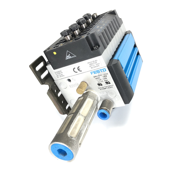
- Page 1 Compact performance Description Electronics CPV valve terminal with direct connec- tion Field bus protocol: INTERBUS-Loop Direct connection type CPV..-GE-IL-... Description 175 509 en 0012b...
- Page 3 ....... . . 175 509 E (Festo AG & Co., D-73726 Esslingen, Federal Republic of Germany 2000) Internet: http://www.festo.com...
- Page 4 Contents and general instructions Festo P.BE--CP-IL-EN en 0012b...
-
Page 5: Table Of Contents
....... 2.5.2 Bus configuration without CMD software ......2-14 Festo P.BE--CP-IL-EN en 0012b... - Page 6 ............Festo P.BE--CP-IL-EN en 0012b...
-
Page 7: Designated Use
If used as an explosion-protected operating media, do not disconnect when under tension! Target group This manual is intended for technicians who are trained in control and automation technology, and who have experience in installing, commissioning, programmierung and diagnosing slaves on the INTERBUS. Festo P.BE--CP-IL-EN en 0012b... -
Page 8: Service
Contents and general instructions Service Please consult your local Festo repair service if you have any technical problems. Notes on the use of this manual Please note This manual describes the functioning of the software ver- sion 1.x and the hardware version 04/98 of the CPV valve terminal with direct connection to the INTERBUS-Loop. -
Page 9: Important User Instructions
... This means that failure to observe this instruction may result in damage to property. The following pictogram marks passages in the text which describe activities with electrostatically sensitive compo- nents. Electrostatically sensitive components may be damaged if they are not handled correctly. Festo P.BE--CP-IL-EN en 0012b... - Page 10 Accessories: Information on necessary or sensible accessories for the Festo product. Environment: Information on environment-friendly use of Festo products. Text markings The bullet indicates activites which may be carried out in any order. 1. Figures denote activities which must be carried out in the numerical order specified.
- Page 11 Special cable for connecting the various CP modules Digital input I/O Module Common term for the CP modules which provide digital inputs andout- puts (CP input and CP output modules) IO/s Digitale In and Output PLC/IPC Programmable logic controller/industrial PC Festo P.BE--CP-IL-EN en 0012b...
- Page 12 Contents and general instructions Festo P.BE--CP-IL-EN en 0012b...
-
Page 13: Installation
Installation Chapter 1 Festo P.BE--CP-IL-EN en 0012b... - Page 14 ............1-18 Festo P.BE--CP-IL-EN en 0012b...
-
Page 15: General Notes On Installation
S the operating voltage supply to the bus terminal S the load voltage supply to the CPV valves You can thereby avoid: – uncontrolled movements of loose tubing – undesired movements of the connected actuators – undefined switching states of the electronic components Festo P.BE--CP-IL-EN en 0012b... -
Page 16: Description Of The Product
Please note Operation of the INTERBUS-Loop requires the appropriate firmware versions in the various INTERBUS master mod- ules. Consult the supplier of the master module for the correct firmware version. Festo P.BE--CP-IL-EN en 0012b... -
Page 17: Installation
24 V DC supply for INTERBUS-Loop INTERBUS-Loop return cable Continuing remote bus Valve coil status LED 24 V DC supply for bus terminal Valve supply connection OUT Incoming remote bus Fig. 1/1: CPV valve terminal in INTERBUS-Loop Festo P.BE--CP-IL-EN en 0012b... -
Page 18: Pin Assignment
DIAG BUS IN + BUS IN - BUS OUT + BUS OUT - 24 V DC valve supply 0 V valve supply Earth connection for valve supply Fig. 1/2: Pin assignment of CPV..-IL valve terminal Festo P.BE--CP-IL-EN en 0012b... -
Page 19: Connecting The Cpv Valve Terminal
The diagram below shows the structure of the Quickonscrew connector. Union nut Crown Sealing rubber Cable cores Splicing ring (2-pin for bus, 3-pin for valve supply) Insulation removed (15 mm) Fig. 1/3: Structure of Quickon screw connectors Festo P.BE--CP-IL-EN en 0012b... -
Page 20: Preparing The Connecting Cable
– the splicing ring for the valve supply is 3-pin 4. Cut off the projecting cable core ends. Make sure that the ends of the cores are flush with the splicing ring. They must not project and must not be too short. Festo P.BE--CP-IL-EN en 0012b... - Page 21 1. Installation Fig. 1/4: Mounting sequence for Quickon screw connectors Festo P.BE--CP-IL-EN en 0012b...
-
Page 22: Connecting The Cables
3. Close the screw connector by tightening the union nut (B). The ends of the cable cores are then pressed into the piercing devices, the core insulation is cut open and elec- trical contact is made. Fig. 1/5: Fitting the connecting cables 1-10 Festo P.BE--CP-IL-EN en 0012b... -
Page 23: Fitting The Blind Plug
2. Insert everything together into the union nut. 3. Place the splicing ring into the non-required connection of the continuing valve supply (C). 4. Place the screw connector upright with the blind plug fitted and tighten the union nut (D). 1-11 Festo P.BE--CP-IL-EN en 0012b... - Page 24 1. Installation Union nut Blind plug Crown Sealing rubber Splicing ring Fig. 1/6: Fitting the blind plug 1-12 Festo P.BE--CP-IL-EN en 0012b...
-
Page 25: Selecting The Power Unit
By using PELV power units, protection against electric shock (protection against direct and indirect contact) in accordance with EN 60204-1/IEC 204 is guaranteed on Festo valve ter- minals. Safety transformers with the adjacent designation must be used for supplying PELV networks. The valve ter- minals must be earthed in order to ensure their function (e.g. -
Page 26: Notes On Connecting The Power Supply
2 A. The supply to the electronic components (via the INTERBUS-Loop) must be fused externally. With the external fuse you can avoid functional damage to the CPV valve terminal if there is a short circuit. 1-14 Festo P.BE--CP-IL-EN en 0012b... - Page 27 1. Installation DIAG 24 V DC valve supply 0 V valve supply Earth connection for valve supply Fig. 1/7: Power supply connection of CPV valve terminal 1-15 Festo P.BE--CP-IL-EN en 0012b...
- Page 28 Make sure that the load voltage lies within the per- mitted tolerance, even during full operation. – Check which connecting variant of the load voltage is suit- able for your application (see following diagram). 1-16 Festo P.BE--CP-IL-EN en 0012b...
- Page 29 ( 2 ). Several CPV valve terminals can still be switched in series within the star- shaped arrangement ( 3 ). Fig. 1/8: Connecting variants for the load voltage of the CPV valve terminals 1-17 Festo P.BE--CP-IL-EN en 0012b...
-
Page 30: Earthing
CPV valve terminal and the earth cable on the load voltage connection have the same potential and that there are no equalizing currents. In this way you can avoid interference due to electromag- netic influences. 1-18 Festo P.BE--CP-IL-EN en 0012b... - Page 31 Commissioning Chapter 2 Festo P.BE--CP-IL-EN en 0012b...
- Page 32 ..........2-26 Festo P.BE--CP-IL-EN en 0012b...
- Page 33 The examples used here for the screen displays have been taken from CMD software version 4. Further and current information can be found in the man- uals for the CMD software and for your control system. Festo P.BE--CP-IL-EN en 0012b...
- Page 34 NOMINAL and ACTUAL configurations in order to recognize connection faults. access these specifications again during the addressing and syntax check, in order to avoid addressing faults. Please note here the information in the following sections. Festo P.BE--CP-IL-EN en 0012b...
- Page 35 Or switch on the power supply in the following se- quence: 1. The power supply for all the field bus slaves or all active bus segments. 2. Then the power supply for the controller. Festo P.BE--CP-IL-EN en 0012b...
- Page 36 Number of outputs and ID code Please note The CPV valve terminal occupies 8 or 16 outputs, depend- ing on the equipment fitted, i.e. the number of valve plates and the type of valve plates. Festo P.BE--CP-IL-EN en 0012b...
- Page 37 CMD software. In the following it is assumed that the user is familiar with the contents of the CMD manual. Please note The CPV valve terminal with an INTERBUS-Loop module can only be added to an appropriate bus terminal (e.g. IBS SL 24 BK-T). Festo P.BE--CP-IL-EN en 0012b...
- Page 38 Inserting with the Ident code Open the dialogue window of the bus terminal for the INTERBUS-Loop. Select the option “Insert with Ident code..” Fig. 2/1: Inserting bus slaves with the Ident code The following dialogue window will then appear: Festo P.BE--CP-IL-EN en 0012b...
- Page 39 Type Ident-Code Process data channel (outputs) CPV10-GE-IL-8 16 Bit CPV14-GE-IL-4 8 Bit CPV14-GE-IL-8 16 Bit Slave type: The default entry Local bus device can be entered. Save these entries with OK. Festo P.BE--CP-IL-EN en 0012b...
- Page 40 In the following input mask you can describe the slave and enter specific information on the CPV valve terminal, e.g. station name and a picture of the slave. Fig. 2/3: Dialogue window “Insert Device Description” 2-10 Festo P.BE--CP-IL-EN en 0012b...
- Page 41 Open the dialogue window “Picture...,” if you wish to use specific icons for the Festo valve terminal. Please note The specific iconsIcons of the Festo valve terminals of the Festo valve terminals can be found on the accompanying CD-ROM. S Read the text “Readme.txt” on the CD-ROM, for a quick survey of the contents of the CD-ROM.
- Page 42 Proceed as follows: Change from one installed icon file to the other with the box “Select ..” Select the file Festo.ICL. Mark icon 6 (it corresponds to your CPV valve terminal for the INTERBUS-Loop). Enter this icon with OK.
- Page 43 Types 03-05 only with valves and/or outputs Type 02 with inputs and outputs Type 02 only with valves Type 10 CPV with INTERBUS-Loop When all the entries have been made, the valve terminal will be integrated into your bus structure. 2-13 Festo P.BE--CP-IL-EN en 0012b...
- Page 44 INTERBUS-Loop for the logical addressing. These con- figuration lists contain at least the following entries: – the ID codes of all the slaves – the logical addresses of all the slaves – the number of inputs – the number of outputs 2-14 Festo P.BE--CP-IL-EN en 0012b...
- Page 45 Assign a logical OUT address and, depending on the type of your valve terminal, 8 or 16 bit outputs to each CPV valve terminal. Type Ident-Code Process data channel (outputs) CPV10-GE-IL-8 16 Bit CPV14-GE-IL-4 8 Bit CPV14-GE-IL-8 16 Bit 2-15 Festo P.BE--CP-IL-EN en 0012b...
- Page 46 Please note Depending on the type of valve terminal, the CPV valve terminal occupies 8 or 16 outputs. Type Ident-Code Process data channel (outputs) CPV10-GE-IL-8 16 Bit CPV14-GE-IL-4 8 Bit CPV14-GE-IL-8 16 Bit 2-16 Festo P.BE--CP-IL-EN en 0012b...
- Page 47 3rd.- 5th. slave: CPV10 valve terminals with 16 outputs 1st. slave 2nd. slave 3rd. slave 4th. slave 5th. slave xxx2 IBS SL 24 .. CPV...IL CPV...IL CPV...IL Process data channel bits Physical BA+32 BA+32+0 BA+32+0+16 BA+32+0+16+16 address BA = Basic address 2-17 Festo P.BE--CP-IL-EN en 0012b...
- Page 48 CPV valve plates. 12-13 14-15 10-11 Fig. 2/5: Address assignment of a CPV valve terminal Please note The following applies: ® pilot solenoid 14 Lower value address Higher value address ® pilot solenoid 12 2-18 Festo P.BE--CP-IL-EN en 0012b...
- Page 49 S Note the assignment of the high and low bytes when assigning the addresses, as the position of these bytes may be swapped when certain control systems are used. In this way you will avoid errors in addressing the valve ter- minal. 2-19 Festo P.BE--CP-IL-EN en 0012b...
- Page 50 0-7 of the valve terminal, byte n+1 on the next coils (8-15). – In the Standard mode the lower value output byte (byte n) is mapped on valve coils 8-15 of the valve terminal, byte n+1 on coils 0-7. 2-20 Festo P.BE--CP-IL-EN en 0012b...
- Page 51 2. Commissioning Example of Siemens mode The following diagram shows the assignment of the CPV valve coils to the addresses in Siemens mode. DIAG Fig. 2/6: Assignment of the valve coils (Siemens mode) 2-21 Festo P.BE--CP-IL-EN en 0012b...
- Page 52 2. Commissioning Example of Standard mode The following diagram shows the assignment of the CPV valve coils to the addresses in standard mode. DIAG Fig. 2/7: Assignment of the valve coils (Standard mode) 2-22 Festo P.BE--CP-IL-EN en 0012b...
- Page 53 Add your CPV valve terminal to your bus structure (necessary steps see section 2.5.1 “Bus configuration with CMD software”). Use the right-hand mouse key to open the dialogue win- dow of the inserted CPV valve terminal. Select the option “Process data.” 2-23 Festo P.BE--CP-IL-EN en 0012b...
- Page 54 2. Commissioning Fig. 2/8: Option for entering the process data 2-24 Festo P.BE--CP-IL-EN en 0012b...
- Page 55 The following dialogue window shows the entries required for swapping/correcting the assignment of the high byte and low byte (example: byte swap for Standard mode). Fig. 2/10: Byte swap correction – example of Standard mode 2-25 Festo P.BE--CP-IL-EN en 0012b...
- Page 56 Please note All the valves on a CPV valve terminal can be prepro- cessed. Periphery fault (PF) The Festo CPV valve terminal on the INTERBUS-Loop does not generate a periphery fault. 2-26 Festo P.BE--CP-IL-EN en 0012b...
- Page 57 Diagnosis Chapter 3 Festo P.BE--CP-IL-EN en 0012b...
- Page 58 Reaction to faults in the control system ......Festo P.BE--CP-IL-EN en 0012b...
-
Page 59: Diagnosis
Diagnosis via the built-in LEDs (see Chapter 3.2). – bus status (DIAG, green) – status of the load voltage supply (US, green) – valve status display (valve coils 12 and 14, yellow) – Diagnosis via the INTERBUS diagnostic status register (see Chapter 3.3). Festo P.BE--CP-IL-EN en 0012b... -
Page 60: Diagnosis Via Leds
The LEDs on the CPV valve terminal indicate the operating and/or error status. DIAG Bus status/error LED “DIAG” Power supply LED (load voltage supply) “US” Valve status display Fig. 3/1: Diagnosis LEDs of the CPV valve terminal Festo P.BE--CP-IL-EN en 0012b... -
Page 61: Normal Operating Status
1) 17,7 V as from hardware version May 1998 17,1 V up to hardware version April 1998 Please note A voltage failure or an undervoltage in the load voltage of the CPV valve terminal does not produce a periphery fault (PF) on the INTERBUS-Loop. Festo P.BE--CP-IL-EN en 0012b... -
Page 62: Error Display (Diag)
Only as from hardware status May 98. Please note The voltage supply of the INTERBUS-Loop and the load voltage supply of the valves are monitored separately. Only the bus undervoltage produces an error message on the INTERBUS module. Festo P.BE--CP-IL-EN en 0012b... -
Page 63: Displays Of The Valve Coils
S basic position S load voltage supply of valves lies below the permitted tolerance range ( < 20.4 V DC) or S fault in compressed air supply or S pilot exhaust blocked or S return for servicing Festo P.BE--CP-IL-EN en 0012b... -
Page 64: Diagnosis Via Interbus
Please note An undervoltage in the 24 V load voltage supply for a CPV valve terminal does not trigger an error message on the INTERBUS-Loop. Festo P.BE--CP-IL-EN en 0012b... -
Page 65: Error Treatment
– unilaterally-actuated valves move to the basic position – bilaterally-actuated valves remain in their current posi- tion – mid-position valves move to mid-position (depending on the valve type: pressurized, exhausted or blocked). Festo P.BE--CP-IL-EN en 0012b... - Page 66 3. Diagnosis 3-10 Festo P.BE--CP-IL-EN en 0012b...
- Page 67 Technical appendix Appendix A Festo P.BE--CP-IL-EN en 0012b...
- Page 68 ........... . Festo P.BE--CP-IL-EN en 0012b...
-
Page 69: Technical Appendix
T 80 °C (year of manufacture see Ex mark on Pro- disconnect when under tension! duct) Valves see Pneumatics manual type P.BE-CPV-... Cable connection: PG11; 1.5 mm £ 1.5 A – current loading Load voltage PG13.5; 1.5 mm – current loading 10 A (max.) Festo P.BE--CP-IL-EN en 0012b... - Page 70 – PCB address range – – Register length on the bus 8 Bit – Length code 1 (1 hex. – Extended local bus diagnosis Peripheral diagnostic messages Bus undervoltage (0BC2) Excess temperature (0BC3) Peripheral error (0BB1) Festo P.BE--CP-IL-EN en 0012b...
- Page 71 200 m – max. ring current 1.8 A 1.8 A – earthing FE load voltage con- FE load voltage con- nected capacitively to nected capacitively to valve terminal valve terminal – diagnostics Slave diagnosis Slave diagnosis Festo P.BE--CP-IL-EN en 0012b...
- Page 72 *) The CPV valve terminal with direct connection for INTERBUS-Loop type CPV..-GE-IL-... can also be used in residential areas with special permission (living, business and commercial areas, small firms). Technical specifications on the pneumatic components can be found in the “Pneumatics manual, P.BE-CPV-...”. Festo P.BE--CP-IL-EN en 0012b...
-
Page 73: Accessories
The connections to the bus and to the load voltage are made in the form of Quickon screw connectors. You can order a complete set (each for one CPV valve terminal) from Festo. Type: Connection set, part no. 175 485... -
Page 74: Dimensions
Dimensions of CPV basic unit with INTERBUS-Loop direct connection 70 mm(2.756 in.) 110 mm (4.331 in.) Type CPC10-GE-IL-8 71 mm 64 mm 110 mm CPC14-GE-IL-4 89 mm 64 mm 96 mm CPC14-GE-IL-8 89 mm 64 mm 152 mm Festo P.BE--CP-IL-EN en 0012b... - Page 75 Index Appendix B Festo P.BE--CP-IL-EN en 0012b...
- Page 76 B. Index Festo P.BE--CP-IL-EN en 0012b...
- Page 77 ....... 1-10 Connecting the operating voltage ....1-14 Festo P.BE--CP-IL-EN en 0012b...
- Page 78 ......Icons of the Festo valve terminals ....
- Page 79 ......... . Switching-on instructions ......Festo P.BE--CP-IL-EN en 0012b...
- Page 80 ......Total current consumption ......1-14 Festo P.BE--CP-IL-EN en 0012b...
Need help?
Do you have a question about the CPV GE-IL Series and is the answer not in the manual?
Questions and answers