
Subscribe to Our Youtube Channel
Related Manuals for GESTRA Gestramat CW 41


Summary of Contents for GESTRA Gestramat CW 41
- Page 1 Gestramat Cooling-Water Control Valve CW 41 CW 41/4 MCW 41 MCW 41/4 Original Installation Instructions 819468-01...
-
Page 2: Table Of Contents
Contents Foreword ............................3 Availability ............................. 3 Formatting features in the document ...................... 3 Directions in this manual ........................3 Safety ..............................3 Use for the intended purpose ......................... 3 Basic safety notes ..........................4 Information on property damage or malfunctions ..................4 Qualification of personnel ........................ -
Page 3: Foreword
Formatting features in the Foreword document This installation & operating manual will help you use the following types of equipment safely and Certain text elements of this installation & operating efficiently for their intended purpose. manual feature a specific typographic design. You ... -
Page 4: Basic Safety Notes
Correct use includes compliance with the Selecting suitable lifting gear and instructions given in this installation & operating understanding the rules for its safe use. manual, in particular obedience to all safety Working with dangerous (contaminated, hot instructions. or pressurized) fluids. -
Page 5: Qualification Of Personnel
Qualification of personnel Typographic features of warning notes A qualified person must be acquainted with and experienced in the following: the pertinent on-site rules and regulations for DANGER preventing fire and explosions as well as industrial safety regulations Notes with the heading DANGER warn against imminent dangerous situations that ... -
Page 6: Description
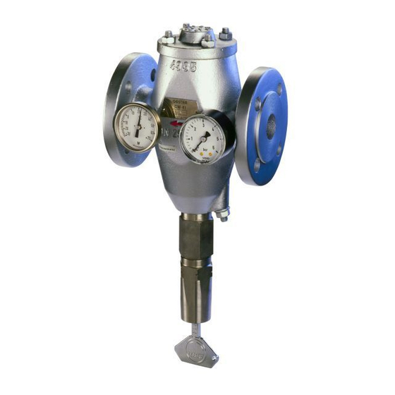
Thermometer with sealing ring Description Pressure gauge Scope of supply and equipment Adjusting key specification The diagrams below show a type CW 41 DN25 device. Scope of supply The following equipment parts are not installed on delivery, and must be fitted before assembly: Equipment specification Designation Designation... - Page 7 Designation Designation Spring Double cone Thermostat (diagram shows model DN25 Pin of adjuster with one thermostat) Pin for setting the bleed flow Optional extras The following items are available as optional extra: The double cone is available in two versions: ...
- Page 8 There are three types of solids thermostat for MCW 41 and MCW 41/4 with diaphragm different outlet temperatures: actuator n-thermostat with rubber elastic expansion The diaphragm actuator (15) is mounted on the lid material for an outlet temperature from +3 to (1).
- Page 9 Name plate ATEX Directive The following items are indicated on the name CW 41 and CW 41/4 plate: The equipment does not have its own potential Manufacturer ignition source and is not subject to this directive Type designation (see "Manufacturer's Declaration"...
-
Page 10: Task And Function
Task and function with s-cone, the bleed flow is directed via the lower seat. Purpose To set the desired return temperature, use the adjuster (6). The currently set return temperature is Cooling-water control valves are directly actuated displayed on a scale on the adjusting key. proportional controllers. -
Page 11: Storing And Transporting The Equipment
Storing the equipment MCW 41 and MCW 41/4 The diaphragm actuator (15) is driven by Please observe the following items when storing compressed air. When operated, the diaphragm the equipment: actuator lifts a spindle (17). The spindle completely opens the double cone. Impurities are therefore ... -
Page 12: Mounting And Connecting The Equipment
To lift equipment the weight of which exceeds Keep the sealing plugs and the packing for approx. 25 kg, you need the help of a second further use. person or suitable lifting gear. Your physical strength and on-site regulations and DANGER conditions determine what weight can be lifted and if support is required. -
Page 13: Attaching Parts To The Equipment
The following tools are required for working on the Lubricate all threads and the contact surfaces of equipment: nuts and bolts with temperature-resistant lubricant. Torque wrench 10–100 Nm to DIN ISO 6789 The lubricant must have the same properties as ... -
Page 14: Connecting The Equipment
Connecting the equipment CAUTION The equipment can be connected in any installation position. Installation with a horizontal direction of Do not drop the equipment. If it falls down flow and the adjuster hanging down ensures it may cause bruises and injuries. optimum function. -
Page 15: Operation
Mount the equipment in the desired installation If the scale value does not match the desired outlet position. temperature, you can change the setting. The table overleaf contains the scale values for the outlet Connect the end connections of the equipment temperatures of the various types of equipment. - Page 16 Desired outlet temperature [°C] Scale value DN25 DN40, DN50 DN80, DN100 Equipment option gauge – – – – – – – – – – – – – – – – – – – – – – – – – – –...
-
Page 17: Setting The Bleed Flow
Setting the bleed flow After operation On delivery, the bleed flow setting screw is set in such a way that the double cone is not lifted. DANGER To set a higher bleed flow, proceed as follows: If fluid escapes personnel may suffer ... -
Page 18: Removing External Dirt Deposits
In the event of back pressure, you must also If there is a risk of freezing, you must block off the drainage line downstream of the completely drain the equipment after equipment. operation. The screw plugs opposite the thermometer and To do this, you can install a drainage valve pressure gauge feature a hole. -
Page 19: Servicing The Equipment And Installing Spare Parts
Servicing the equipment and installing spare parts You may exchange the following component parts in case of wear or damage: Spare parts for CW 41... - Page 20 Nominal size DN25 DN40, DN50 DN80, DN100 Name Order number Body gasket 184372 184373 184374 Spring 004950 004981 030001 Adjuster, complete 004953 Thermometer 184596 Pressure gauge 004704 w-thermostat 004941 n-thermostat 030040 k-thermostat 030042 Double cone s-cone 004940 004980 030000 r-cone, complete 184283 184288 184292...
- Page 21 Spare parts for CW 41/4...
- Page 22 Nominal size DN25 DN40, DN50 DN80, DN100 Name Order number Body gasket 184372 184373 184374 Spring 004950 004981 030001 Adjuster, complete 004953 Thermometer 184596 Pressure gauge 004704 w-Thermostat 184427 n-Thermostat 184428 k-Thermostat 184429 Double cone s-cone 030984 030987 030990 r-cone, complete 184348 184351 184352...
- Page 23 Spare parts for diaphragm actuator DANGER No spare parts are available for the diaphragm actuator. In the event of damage, please replace Personnel working on pipes are exposed to the complete diaphragm actuator. safety risks and may suffer severe injuries, poisoning or even loss of life.
- Page 24 DANGER If fluid escapes personnel may suffer severe injuries, poisoning or even loss of life. After working on the equipment make sure that all connections and valves are tight. Make sure that the gaskets of the body are leakproof. CAUTION Do not drop the equipment.
- Page 25 Removing the double cone CAUTION Risk of injury from lid under spring pressure. Before unscrewing the hex nuts, reduce the spring tension in the equipment by slackening the setting screw and adjuster. Completely unscrew the setting screw (7). ...
- Page 26 Using needle-nose pliers, squeeze the ends of To remove the double cone from the body, proceed the circlip (25) together. as follows: Take the circlip out of the grooves (32). Screw the adjusting key (21) into the body completely.
- Page 27 Installing the double cone Lubricate all threads and the contact surfaces of nuts and bolts with temperature-resistant lubricant. Attention! The lubricant must have the same properties as Equipment may leak if the gasket is ® 217. damaged. Mount the lid on the four setscrews on the body ...
- Page 28 Replacing the diaphragm actuator Take the double cone out of the body. The diaphragm actuator must be removed or Take the thermostats out of the double cone, as installed in the following cases: described on page 26. To replace a faulty diaphragm actuator ...
-
Page 29: Troubleshooting
Troubleshooting Problem Cause Remedy The flow rate is too low. The size and design of the Change the equipment settings. equipment differs from the The planned return Check the equipment size. system data. temperature is not reached. Use equipment of a size that conforms to the system data. -
Page 30: Putting The Equipment Out Of Operation
Putting the equipment out of Caution operation Environmental damage may be caused by Removing harmful substances poisonous fluid residues. Before disposing of the equipment DANGER make sure that it is clean and free of fluid residues. If the equipment is used in contaminated ... -
Page 31: Re-Using Equipment After Storage
CAUTION Risk of injuries if the equipment falls down. When removing the equipment make sure the it is safely held in place and cannot fall down. Suitable measures are for instance: Equipment that is not too heavy may be supported by a second person. -
Page 32: Disposing Of The Equipment
Disposing of the equipment Caution Environmental damage may be caused by poisonous fluid residues. Before disposing of the equipment make sure that it is clean and free of fluid residues. For the disposal of all materials observe the pertinent legal regulations concerning waste disposal. -
Page 33: Technical Data
Technical data Dimensions and weights CW 41 and CW 41/4 Weights and dimensions for flange connection PN 16/CL125: Nominal size DN25 DN40 DN50 DN80 DN100 L [mm] W [mm] H1 [mm] H2 [mm] Weight [kg] Dimensions for flange connection PN 16/CL125, weights for flange connection EN PN 16: Nominal size 1 "... - Page 34 MCW 41 and MCW 41/4...
- Page 35 Weights and dimensions for flange connection PN 16/CL125 Nominal size DN25 DN40 DN50 DN80 DN100 L [mm] W [mm] H1 [mm] H2 [mm] Weight [kg] 36.5 37.5 Dimensions for flange connection PN 16/CL125, weights for flange connection EN PN 16: 1 "...
-
Page 36: Pressure & Temperature Ratings
Pressure & temperature ratings Operating limits for flange PN16 and drilled flange CL125 Pressure and temperature: Limit values for body/hood to EN 1092-2 Pressure p [barg] Temperature T [°C] –10/20 Maximum differential ΔPMX [bar] pressure ΔPMX [psi] Maximum allowable TMO [°C/°F] n-thermostat: 100 °C/212 °F operating temperature w-thermostat: 60 °C/140 °F... -
Page 37: Manufacturer's Declaration
Assessment according to European rules refer to our Declaration of Conformity or our Declaration by Manufacturer. To download the current Declaration of Conformity or Declaration by Manufacturer go to www.gestra.com/documents or contact: GESTRA AG Münchener Straße 77 28215 Bremen Germany... - Page 40 Agencies all over the world: www.gestra.de GESTRA AG Münchener Straße 77 28215 Bremen Germany Telefon +49 421 3503-0 Telefax +49 421 3503-393 E-Mail info@de.gestra.com www.gestra.de 819468-01/07-2017 kx_mm (802993-02) © GESTRA AG Bremen Printed in Germany...
Need help?
Do you have a question about the Gestramat CW 41 and is the answer not in the manual?
Questions and answers