
Summary of Contents for MH Corbin Connect:ITS
-
Page 1: Mh Corbin Connect:its User Manual
MH Corbin Connect:ITS User Manual Version 3.6 September 21, 2020 MH Corbin 6077 Frantz Rd Ste 203 Dublin OH 43017 800-380-1718 https://mhcorbin.com... - Page 2 The right to print or otherwise make available copies of the documentation is limited to the period during which the applicable license for such software remains in full force and effect. Should the license terminate for any reason, it is your responsibility to certify in writing to MH Corbin that all copies and partial copies of the documentation have been returned to MH Corbin or destroyed.
-
Page 3: Table Of Contents
Table of Contents MH Corbin Connect:ITS User Manual ................ 1 Table of Contents ...................... 3 Installation ....................... 7 Mounting ......................7 Power Hook Up ..................... 7 Indicators and Connectors ..................7 Connect:ITS 19 ......................7 Front Panel LEDs ...................... 7 Front Panel Connectors.................... - Page 4 Ping Remote Host ..................... 19 SNMP and NTCIP Parameters ................... 19 Configure V2I RSU Parameters Pre FW 1.0.42 ............20 Configure Lidar (Requires FW Restart) ..............21 Configure Metiri and Telegraf (Requires FW Restart) ..........22 Metiri Application Snapshot Overview ..............24 Watchdog Properties ....................
- Page 5 WS300UMB ....................... 46 WS400UMB ....................... 46 WS500UMB ....................... 46 WS600UMB ....................... 47 VS2KUMB ........................47 NIRS31UMB ....................... 48 MARWIS StaRWIS ...................... 49 MH Corbin ......................49 VX21 .......................... 49 Vaisala ........................ 49 DSC111 ........................49 Wavetronix HD ....................50 HD125 ........................50...
- Page 6 HD125 Periodic ......................50 Appendix B – Database Schema ................51 Change Log ......................53...
-
Page 7: Installation
6” W, and it weighs approximately 1.5lbs. It is recommended to install by placing the top mount point of the Connect:ITS with the spring on the top of the rail first. While pressing the top of the Connect:ITS down swing the bottom part of the mount inwards toward the rail. -
Page 8: Front Panel Connectors
Front Panel Connectors Front Panel Connectors RS485 #1, 2 Sensor Input connector for sensors that utilize the RS485 serial data connections. RS232 #1, 2 Connector for RS232 sensors. USB #1, 2 Connector for USB sensors. Cell Antenna connector for internal cellular modem. Antenna connector for internal cellular GPS. -
Page 9: Rear Panel Connectors
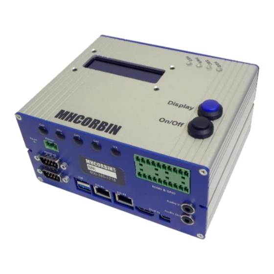
Displays unit information IP address, IP Mode, CPU Temp (C), Firmware Version Display Button This button allows user to cycle through pertinent system information such as: IP address, IP Mode, CPU Temp (C), Firmware Version. ON/OFF This button turns the Connect:ITS DIN on and off ___________________________- 9 - ___________________________... -
Page 10: Display Button Modes
Display Button Modes Display Button Modes First IP Address for Eth #1 CPU Temperature shown as Celsius. Can be changed to Fahrenheit in Setup. IP Address Type shown as Static. Can be changed to DHCP in Setup. Firmware Version Front Panel LEDs ___________________________- 10 - ___________________________... -
Page 11: Bottom Panel Connectors
Front Panel LEDs Flashes orange during disk activity Lights green when the internal computer has powered up Lights green when the unit is receiving power from the backplane Flashes blue when unit is operating normally Bottom Panel Connectors Antenna Connectors Antenna Connectors Cell Antenna connector for internal cellular modem... -
Page 12: Exploded View Of Rs485 / Gpio Pinout
Antenna Connectors Antenna connector for internal cellular modem Antenna connector for internal cellular GPS Antenna connector for internal Iridium satellite communications module Antenna connector for 915Mhz internal radio Exploded View of RS485 / GPIO Pinout RS485 / GPIO Pinout ttyXRO, ttyXR1, Sensor Input connector for sensors that utilize the RS485 serial data ttyXR2 and ttyXR3 connections... -
Page 13: Rs232 Connectors
RS232 Connectors RS232 Connectors ttyS0 and Sensor Input connector for sensors that utilize ttyS1 the RS232 serial data connections USB Connectors USB Connectors USB connectors for sensors that utilize USB data connections Power Connector Power Connector Two pin Phoenix style power connector. Supports 12-24 VDC Ethernet Ports Ethernet Ports ___________________________- 13 - ___________________________... -
Page 14: Display And Audio Connectors
Ethernet Ports Dual ethernet ports with bridging capability Display and Audio Connectors Display and Audio **reserved for future use** ___________________________- 14 - ___________________________... -
Page 15: Setup / Modem Physical
Setup / Modem Physical Modem Top View (circled in orange is the Modem Bottom View modem number for Modem drop down) Modem Mounts to Board with Antenna Connectors Facing Inwards Where Silk Screen Reads: U6 Cellular Xbee ___________________________- 15 - ___________________________... -
Page 16: Vx 21 Wireless Radio Install
It can be added on to an existing RWIS system or it can be used with our Connect:ITS product. The Connect:ITS line uses a VXMS Receiver Radio to communicate with the VX 21. In North America the module uses a 900 Mhz frequency for communication. -
Page 17: Administration
Open a web browser and navigate to the Connect:ITS URL using the following format: https://{ipaddress} If successful, you will be presented with the Connect:ITS login page. Click on the Login link. Enter the username and password, by default these are factory set to control, control... -
Page 18: Control Page
Control Page The default Control page shows the system status: The digital outputs of the Connect:ITS can be toggled on or off using the buttons in the right column. ___________________________- 18 - ___________________________... -
Page 19: Setup Page
Enter the "setup" username and password. The default passwords are located in the Administration section of this manual. Location Enter location description, or name to identify this Connect:ITS unit, latitude, longitude and altitude information. Ping Remote Host By entering a valid IP address of a host machine we can ensure that a connection between that host and the Connect:ITS is able to ping properly. -
Page 20: Configure V2I Rsu Parameters Pre Fw 1.0.42
Configure V2I RSU Parameters Pre FW 1.0.42 These settings work with the Intellizone application. A guide has been provided in the following table. V2I RSU Parameters Pre FW 1.0.42 RSU Type Compatible with 4.1 AM spec unless otherwise specified: Siemens ESCoS (SNMP) Cohda Wireless MK5 Savari SW100 TrafficCast BlueTOAD Spectra... -
Page 21: Configure Lidar (Requires Fw Restart)
The Connect takes incoming RSU uper data on this port and converts it to XML to be sent to the designated Forward IP. Forward IP:Port (CSV) Database IP Address or addresses that the Connect:ITS is to forward to. Data sent is encoded XML. Example: 192.168.200.5:8990,192.168.200.22:9191 Forward Endpoint Websocket use. -
Page 22: Configure Metiri And Telegraf (Requires Fw Restart)
Introducing Metiri as of firmware release 1.0.35. Metiri is a separate dashboard and time series database allowing you to gather insights from your lidar, camera, and/or sensor data. Demonstrations are available upon request. Speak with an MH Corbin consultant to set up a demonstration as well as licensing information. - Page 23 This monitors the stats of the Connect:ITS cpu and is useful for quickly CPU Stats identifying high loads on the device. Include Telegraf This monitors the stats of the Connect:ITS disk stats and is useful to see how disk stats much space is left on the harddrive. Include Telegraf This monitors the stats of the Connect:ITS kernel.
-
Page 24: Metiri Application Snapshot Overview
Configure Metiri Include Telegraf This monitors the stats of the Connect:ITS cpu temperatures. temp stats Metiri Application Snapshot Overview Figure 1, Metiri Intellizone Data for Pedestrian, Collision, Wrong Way, Queue, Work zone Alerts, including Snapshots or Video Alert Options Figure 2, Metiri Pedestrian Alert Counts... -
Page 25: Watchdog Properties
Figure 4,Example of a Threshold Alert that can Trigger multiple forms of Figure 5, Example of Corresponding Alert Panel output including email. Watchdog Properties System watchdog monitors Connect:ITS firmware and reboots the device if the firmware stops responding. By default system watchdog is disabled. ___________________________- 25 - ___________________________... -
Page 26: Disabling Items On Display Screen: Ip Address
These buttons allow a few different ways to restart or reinitialize the device: • Reboot button performs soft reboot of the device. This restarts both operating system and the Connect:ITS firmware. • Restart button performs restart of the Connect:ITS firmware only without restarting the operating system. ___________________________- 26 - ___________________________... -
Page 27: System Info
System information such as CPU Temp (C), Kernel Release, and Uptime can be viewed here. Setup/IP Page The Connect:ITS supports two IPv4 network ports through DHCP and Static addressing. From the factory, the unit comes with a static IP configured. -
Page 28: Nameserver
Nameserver The name server field allows you to point the Connect:ITS to the DNS server of your choice. Works for either an organizations internal DNS servers or a public DNS server like Googles famous “8.8.8.8”. -
Page 29: Setup/Logging Page
The Debug log provides verbose information about the system. This information is important for troubleshooting issues that may arise. A MH Corbin technical support personnel may have you select debug mode and copy the log file and send it to them for troubleshooting purposes. -
Page 30: Error Log
Error Log As of FW 1.41 a new mode of logging was introduced. Error logging allows the user to quickly zero in on items that are causing application errors. Setup/Password Page Use this form if you want to change the default passwords for the Control and Setup page. MHC recommends that you change the passwords since the default passwords are published. -
Page 31: Setup/Firmware
Same as Setup Setup/Firmware This page allows users to check Connect:ITS and its hardware components firmware versions as well as to install Connect:ITS firmware updates. Once the new firmware image has been selected, the SUBMIT button will load the new image and reboot the Connect:ITS. -
Page 32: Firmware Failure To Update And Resolution
• Try reinstalling the firmware • In the event that this also fails use the main MH Corbin phone number for assistance. Successful Firmware Update and 502 Error At the end of a successful firmware update if the page is refreshed too soon it is possible to encounter a 502 error as shown below. -
Page 33: Rolling Firmware Back
Newly added as of FW 1.40 is the Height measurement in mm or inches. The Connect:ITS device system time can be set either by entering system time manually or by enabling NTP service functionality which will periodically synchronize system time with the time of the network time server. -
Page 34: Setup/Its Sensors Page
Setup/ITS Sensors Page This page allows users to setup various ITS sensors so that the Connect:ITS can communicate with them and collect data. Sensors Connect:ITS can be configured for a variety of different sensors. A current list is included at the beginning of the manual. -
Page 35: Adding New Sensors
Configure Sensor Polling Polling Interval Used as the data collection interval for all configured sensors. If this box value is set to zero, data collection is disabled. Units are in seconds so a typical value might be 600 (which is 10 minutes). In the screenshot above we have established a value of 5 seconds for the polling interval. -
Page 36: Adding New Serial Sensor
10. If all ports have been tried, it is possible that the Device ID being used is incorrect. Some sensors share a port, such as the MH Corbin VX 21 sensor. In these cases, the same port can be assigned to multiple sensors, but typically each sensor is assigned a different port. -
Page 37: Removing Configured Sensors
Setup/Modem Page As an option, an internal modem can be installed into the Connect:ITS system. This can provide an off- network Connect:ITS data access without the need to purchase an additional equipment. After installation of the internal modem, the modem is setup for operation by clicking on the Modem tab:... -
Page 38: Step 1 - Ppp Peer Port
To change, just select the serial port the modem is using and click Submit. NOTE: On a Connect:ITS DIN, the default port should be /dev/ttyUSB4. You only need to change this setting as directed by MH Corbin support or if the modem port has changed since factory setup. -
Page 39: Step 3 - Ppp Chat Script
NOTE: TC4NAG modems require doing this step up to 3 times. The first pass sets a USB communication mode, the second pass sets the ATT/VZW firmware mode, the third pass sets the activation context. NOTE: The modem needs to have IMEI and be activated by Verizon. This step only needs to be completed if the modem has not been provisioned before or if the modem has been replaced. -
Page 40: Step 7 - Change Default Route Step 7
Frequently used Modem APN Strings This is not a comprehensive list, but here are APN strings commonly used by MH Corbin. Knowing which APN string to use depends on either the customer, or who purchased the SIM card, or where the SIM card was ordered. -
Page 41: Creating Scripts
New scripts can be created either by uploading existing Python script files using “Upload new script” form or by using Connect:ITS built in editor in which case the script entry would have to be created first using “Create new script” form:... - Page 42 Once the scripts are either uploaded or created they will be displayed in the “Existing scripts” list: To enable a particular script, click the radio button next to the script you want to enable, then Click Start. To stop a script from running simply Click Stop, The Disable button will stop the script from being executed automatically.
-
Page 43: Applications
The Connect:ITS has Restful API’s created for different events depending on the scenario and licensing. Currently the API’s authenticate using Basic Access Authentication. Some are listed in the Intellizone Camera input, however, a more extensive list can be found in the Connect:ITS helpful API guide located as follows:... -
Page 44: Lidar
Connect:ITS (only one device can be attached currently; Application: Wrong Way Detection) and are licensed a new tab will appear in the Connect:ITS menu. This offers a view of the lidar setup and is useful for defining exclusion or inclusion zones and setting up the lidar. More information on Cepton Vista Lidar setup can be found in the Cepton manual included with your purchase. -
Page 45: Appendix A - Sensor Channels
Appendix A – Sensor Channels SX300 Statistical Channel Name Channel Unit Traffic Zone Traffic Volume Traffic Occupancy Traffic Speed Lufft WS100UMB Channel Name Channel Measurement Type (Unit) Precipitation Quantity – Differential Precipitation Type Preciptiation Type: 0 = No Precip 60 = Liquid Precip 70 = Solid Precip 40 = Unspecified Precip WS100UMB Only... -
Page 46: Ws300Umb
WS300UMB Channel Name Channel Unit Air Temperature Celcius -50.0 60.0 Dew Point Temperature Celcius -50.0 60.0 Relative Humidity 100.0 Absolute Air Pressure 1200 WS400UMB Channel Name Channel Unit Air Temperature Celcius -50.0 60.0 Dew Point Temperature Celcius -50.0 60.0 Relative Humidity 100.0 Absolute Air Pressure 1200... -
Page 47: Ws600Umb
Channel Name Channel Unit Absolute Air Pressure 1200 Wind Speed Wind Direction Fast degrees 359.9 Compass degrees WS600UMB Channel Name Channel Unit Air Temperature Celcius -50.0 60.0 Dew Point Temperature Celcius -50.0 60.0 Relative Humidity 100.0 Absolute Air Pressure 1200 Wind Speed Wind Direction Fast degrees... -
Page 48: Nirs31Umb
RS2UMB Channel Name Channel Unit Ambient Temperature Celcius Precipitation Quantity l/m2 Precipitation Type 0 = No precipitation 60 = Rain 67 = Freezing rain 69 = Sleet 70 = Snow 90 = Hail NIRS31UMB Channel Name Channel Unit Road Temperatures Celcius -40.0 70.0... -
Page 49: Marwis Starwis
3 = Ice-Covered 4 = Snow / Ice - Covered 5 = Chemically Wet 6 = Water + Ice 8 = Snow - Covered 99 = Undefined MH Corbin VX21 Channel Name Channel Unit Surface Satus 20000 50 = Chemically Wet 175 –... -
Page 50: Wavetronix Hd
Channel Name Channel Unit Air Temperature Celcius -40.0 60.0 Relative Humidity 100.0 Dew Point Celcius -40.0 60.0 Visibility 11 (21000) Meters 2000 In Voltage 30.0 Surface Temperature Celcius -40.0 60.0 DST Status Surface Status 66 (21001) Grip 68 (21002) DSC Status Water 00.00 99.00... - Page 51 Appendix B – Database Schema The Connect:ITS stores it’s traffic and weather data into a locally running instance of PostgreSQL. There are 2 tables of interest here: Sensor and SensorData. Sensor contains the details to communicate with the device -- Table: public.sensor -- DROP TABLE public.sensor;...
- Page 52 channel), CONSTRAINT sensordata_sensorid_fkey FOREIGN KEY (sensorid) REFERENCES public.sensor (id) MATCH SIMPLE ON UPDATE NO ACTION ON DELETE NO ACTION WITH ( OIDS = FALSE TABLESPACE pg_default; ALTER TABLE public.sensordata OWNER to postgres; ___________________________- 52 - ___________________________...
- Page 53 Version 3.3 Created Upgrade Software Interface Guide v3.3 9/9/2019 Brandon Whitaker Robert Mathis Version 3.4 Skipped for parity with Connect:ITS hardware manual 2/14/2020 Version 3.5 Updated Modem information, added new Metiri 2/20/2020 Robert Mathis section in Setup page, added updated information for Rest API’s, added new photo front page for software...
- Page 54 Version/Author Comments Date Published and Time new Height measurement. BW -> Updated Modem section with new modem directions, restored lost APN’s from manual v3.4, added Appendix B Version 3.5.3 Add V2I RSU Parameters in Setup. Setup/IP add 7/23/2020 Robert Mathis nameserver information.
Need help?
Do you have a question about the Connect:ITS and is the answer not in the manual?
Questions and answers