Kuppersbusch EMW 7505.0 Service Manual
Hide thumbs
Also See for EMW 7505.0:
- Instructions for use manual (7 pages) ,
- Instructions for use manual (7 pages)
Table of Contents
Advertisement
Quick Links
Advertisement
Table of Contents

Related Manuals for Kuppersbusch EMW 7505.0


Summary of Contents for Kuppersbusch EMW 7505.0
- Page 1 e{Š‡yŽ} ‡Ž}† ]eo OMHMFH...
- Page 2 Service Manual: H4-70-14-02 Responsible: D. Rutz KÜPPERSBUSCH HAUSGERÄTE AG Email: dieter.rutz@kueppersbusch.de Phone: (0209) 401-733 Kundendienst Fax: (0209) 401-743 Postfach 100 132 Date: 15.04.2003 45801 Gelsenkirchen...
-
Page 3: Table Of Contents
H4-70-14-02 Contents Safety............................4 Features and installation ......................5 Disposing of the packaging and your old appliance ............5 Features .......................... 5 Technical data ......................... 5 Ventilation........................6 Installation ........................6 Functions ..........................8 Control panel ........................8 Setting the clock ......................8 Timer .......................... -
Page 4: Safety
H4-70-14-02 Safety Danger! All work and repairs may only be carried out by a qualified service technician. Incorrect repairs can be extremely dangerous for the user! To prevent electric shocks, please observe the following tips: • In the event of faults, housing and frame may be live! •... -
Page 5: Features And Installation
H4-70-14-02 Features and installation Disposing of the packaging and your old appliance The packaging material for transport is fully recyclable. Recycling the packaging saves raw materials and reduces the amount of waste. Disposed appliances still contain useful materials. Take your old appliance to a recycling collection point. Please make your old appliances unserviceable before disposing of it, to prevent it from misuse. -
Page 6: Ventilation
H4-70-14-02 Ventilation The appliance has no ventilation slits at the sides of the Ventilation front panel. The air flow takes place as shown in the illustration. Air flow Aspiration Air transport Air transport Aspiration Installation Please see the illustration for the exact installation dimensions. Thickness of the structure 16-21 mm Appliance dimensions Height... - Page 7 H4-70-14-02 Procedure Plug in the appliance and place it in the middle of the cupboard. Fix the product, by turning the screw with a 2mm allen-key, which is coming with the product as shown in the illustration. The microwave oven will be centered and fixed automatically by the new fixing system.
-
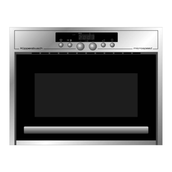
Page 8: Functions
H4-70-14-02 Functions Control panel POWER for setting the power level (0, 160, 350, 500, 750 W) JET DEFROST for selecting “Rapid Defrost” + / - to set weight, time and clock STOP to pause cooking and access test mode START Start of the “Rapid Defrost”... -
Page 9: Cooking And Reheating
H4-70-14-02 Cooking and Reheating Use this function for normal cooking and reheating. Press the PLUS or MINUS button to set the desired time. Press the POWER button repeatedly to set the desired power level. Press the START button. Once the cooking process has been started the time can easily be increased in 30-second steps by pressing the START button. -
Page 10: Rapid Start
H4-70-14-02 Rapid Start This function is used for quick reheating of foods with a high water content such as clear soups, tea ... Press the START button: the appliance starts with full microwave power and the cooking time is set to 30 seconds. -
Page 11: Cleaning
H4-70-14-02 Cleaning Prior to all maintenance or cleaning work always pull out the mains plug and wait until the appliance has cooled down. Please heed the safety instructions on “Components” on page 12. The cooking cavity is made of stainless steel and therefore cleaning is extremely easy. -
Page 12: Components
H4-70-14-02 Components Safety precautions - microwave energy Service technicians must never be exposed to the microwave radiation which can be emitted by the magnetron or other components producing microwaves if the appliance is not connected correctly or is operated improperly. All microwave terminals for input and output, the wave guide and all flanges and seals must be fastened and sealed correctly. -
Page 13: Housing
H4-70-14-02 Housing After removing 11 screws on top and on the sides of the cavity, remove the cover by lifting the sides and pull the cover to the rear. Microswitches The 3 microswitches are mounted on holders on the right side of the door behind the front wall. -
Page 14: Magnetron
H4-70-14-02 Maybe you have to bend the plate (see the small picture on the left) to remove the lower holder. Magnetron To remove the magnetron disconnect the power board, the fan motor connection and the primary connections of the HT-transformer. Remove the support which is fixed with 3 screws from outside (see the arrow) Disconnect the HT-transformer from the magnetron and... -
Page 15: Fan And Fan Motor
H4-70-14-02 Then remove the two screws on the rear panel of the appliance and remove the HT-transformer (see the arrows). Then the magnetron can be disassembled by removing the 4 screws on the side wall (see the arrows). Magnetron with holder, screws and overheat protection (NTC). - Page 16 H4-70-14-02 Then remove the top panel of the fan housing by unclipping it. The wheel can pulled out from housing as shown by the arrow. Behind the fan wheel are two screws to remove the fan motor from the support. After disassembly the fan divides in top panel housing...
-
Page 17: Power Board
H4-70-14-02 Power board Disconnect the power board and remove it with the support (see “Magnetron” on page 14). Then the power board is removable from it’s frame by removing two screws on the board. Safety thermostats The cavity safety thermostat is located in front of the power board at the cavity top panel. -
Page 18: Front Panel And Display
H4-70-14-02 Front panel and display Disconnect the two flat cables from the display on the power board. To disassemble the front panel you have to remove 6 screws (see the arrows and the screwdriver). Remove the 4 screws at the bottom plate of the display and remove the plate too. -
Page 19: Door
H4-70-14-02 Door After removing the front panel remove the screw on top hinge of the door. Open the door, tip it, then lift the door to remove it from the bottom hinge. To disassemble the handle remove the two screws on the inside of the door. -
Page 20: Fixation System And Turntable Motor
H4-70-14-02 5.10 Fixation system and turntable motor To reach the fixation system remove the 6 screws which are highlighted with arrows. Then the back panel can be pulled away. To remove the fixation system lie the microwave oven on the door;... -
Page 21: Measuring The Output Power Of The Magnetron
H4-70-14-02 Measuring the output power of the magnetron The following procedure provides information on the working conditions of the magnetron but it does not reproduce an accurate measurement of the microwave output power. The test load is one litre (1000 ml) of water with a starting temperature of 15 - 24 °C in a container with a capacity of 1000 ml. -
Page 22: Component Check
H4-70-14-02 Component check Magnetron check - Resistance measurement Resistance measurement: Target value: > 1 Ω With ohmmeter (scale Rx1) between the connections of the heating filaments of the magnetron. infinite With ohmmeter at maximum measuring range between each of the heating filament connections and the earthed frame. -
Page 23: Diode
H4-70-14-02 Diode Checking the diode Normal result Create a circuit with 12 V DC and a 2.5 V lamp between The lamp is either on or off, depending on the connections. the direction of current. Diode defective Lamp lights up too brightly: short circuit Lamp is never on: open circuit Microwave leak test This test is to be performed after every type of maintenance work on the door, closing device,... -
Page 24: Troubleshooting
H4-70-14-02 Troubleshooting Every appliance is carefully tested before it leaves the factory. However it is important that it is assem- bled and operated correctly. Despite all safety measures, the safety of the appliance depends on it being correctly installed. It is equally important for the user to operate the appliance correctly and to carry out the appropriate maintenance measures. - Page 25 H4-70-14-02 Fault codes Description ERR A No rollers or rotating plate in the oven. ERR B The weight sensor has no impulse. Sensor defect or not properly connected. ERR C Fuzzy temperature sensor defect or not properly connected. ERR D NTC overheating protection device on the magnetron is defect (not activated or short circuit) DOOR...
-
Page 26: Faults, Causes And Remedy
H4-70-14-02 Faults, causes and remedy Fault Possible Cause / remedy The appliance does not work. • The door is not properly closed. • Check the fuses and check for loose connections. • Check the safety thermostats and their connections. • Check the connection of the black flat cable coming from the control board.
Need help?
Do you have a question about the EMW 7505.0 and is the answer not in the manual?
Questions and answers