Table of Contents
Advertisement
Quick Links
Advertisement
Table of Contents

Subscribe to Our Youtube Channel
Related Manuals for IOtech WaveBook 512


Summary of Contents for IOtech WaveBook 512
- Page 1 Artisan Technology Group is your source for quality new and certified-used/pre-owned equipment SERVICE CENTER REPAIRS WE BUY USED EQUIPMENT • FAST SHIPPING AND DELIVERY Experienced engineers and technicians on staff Sell your excess, underutilized, and idle used equipment at our full-service, in-house repair center We also offer credit for buy-backs and trade-ins •...
- Page 2 WaveBook/512 and WaveBook/512H High-Speed Portable Data Acquisition Systems 481-0901 Rev. © 1999, 2000, 2001, 2002 by IOtech, Inc. April 2002 Printed in the United States of America Artisan Technology Group - Quality Instrumentation ... Guaranteed | (888) 88-SOURCE | www.artisantg.com...
- Page 3 WaveBook User’s Manual 481-0901 Artisan Technology Group - Quality Instrumentation ... Guaranteed | (888) 88-SOURCE | www.artisantg.com...
- Page 4 IOtech, Inc. cannot be held liable for any damages resulting from the use or misuse of this product. Copyright, Trademark, and Licensing Notice All IOtech documentation, software, and hardware are copyright with all rights reserved. No part of this product may be copied, reproduced or transmitted by any mechanical, photographic, electronic, or other method without IOtech’s prior written consent.
- Page 5 &$87,21 Using this equipment in ways other than described in this manual can cause personal injury or equipment damage. Before setting up and using your equipment, you should read all documentation that covers your system. Pay special attention to Warnings and Cautions. ®...
-
Page 6: Chapter 1 - An Introduction To Wavebook And Optional Wbks
About WaveBook Documentation Aside from the WaveBook User’s Manual that is shipped with the product, the documentation listed on the preceding page is also important. The later is not shipped as hardcopy, unless purchased. However, during ® software installation, Adobe PDF versions of the documentation are automatically installed onto your hard drive. - Page 7 WaveBook User’s Manual 03-08-02 WaveBook/512 and WaveBook/512H Artisan Technology Group - Quality Instrumentation ... Guaranteed | (888) 88-SOURCE | www.artisantg.com...
-
Page 8: Table Of Contents
Table of Contents Chapter 1 – An Introduction to WaveBook and Optional WBKs What Are WaveBooks? …… 1-1 What’s the Difference Between WaveBook/512 and WaveBook/512H?…… 1-2 What are WBKs?…… 1-3 How Do WaveBooks and WBKs Interrelate? …… 1-5 How Are WaveBook Systems Powered?…… 1-6 Specifications ……... - Page 9 Chapter 5 – Troubleshooting and Customer Support Electrostatic Discharge (ESD), Handling Notice…… 5-1 Product Care …… 5-1 ReadMe Files and the Install CD-ROM ……5-2 Driver Support……5-2 Connection Problems……5-2 Frequently Asked Questions …… 5-7 Customer Support …… 5-11 Appendix A – Dimensional Drawings Glossary viii WaveBook User’s Manual...
-
Page 10: What Are Wavebooks
An Introduction to WaveBooks and WBKs What Are WaveBooks? …… 1-1 What’s the Difference Between WaveBook/512 and WaveBook/512H ?…… 1-2 What Are WBKs?…… 1-3 How Do WaveBooks and WBKs Interrelate? …… 1-5 How Are WaveBook Systems Powered?…… 1-6 Specifications …… 1-6 What Are WaveBooks? WaveBooks are high-speed portable data acquisition devices that can be used in a variety of applications, such as testing engine strain, multi-channel acoustics, mechanical integrity, and vibration/shock/strain. -
Page 11: What's The Difference Between Wavebook/512 And Wavebook/512H
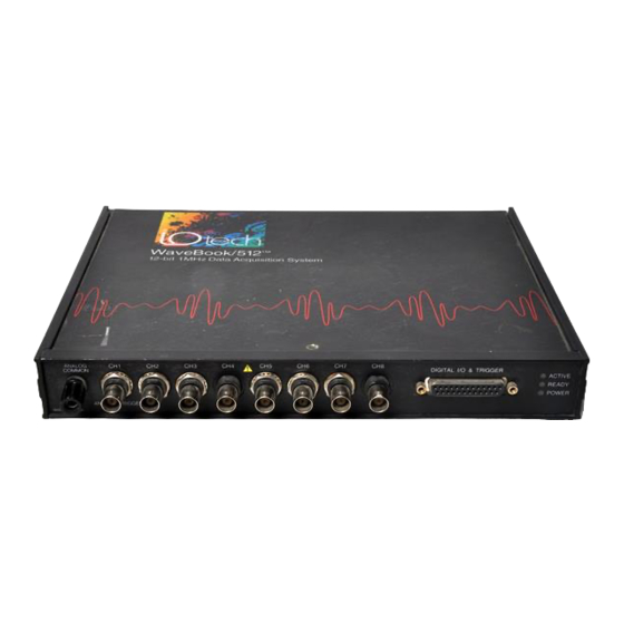
What’s the Difference Between WaveBook/512 and WaveBook/512H ? With exception of having different range values, the WaveBook/512 and WaveBook/512H are identical. Each provides 1 MHz sampling and, with exception of the WBK17 module, supports the WBK options described shortly. WaveBook/512 and WaveBook/512H Analog Input A/D resolution 12-bit... -
Page 12: What Are Wbks
What Are WBKs? You can use various modules and option cards to expand your WaveBook system. These WaveBook options are known as WBKs. Internally, WaveBook has room for one signal-conditioning card. Externally, you can use one or more expansion modules. Reference Note: The WBK option cards and modules that follow are detailed later in this user’s manual. - Page 13 WBK16 is an 8-channel strain-gage signal-conditioning module. Up to eight WBK16 modules (64 channels) can be accommodated by the WaveBook and scanned at 1 µs/channel. Almost all bridge configurations are supported via a bridge-completion network and software. High-gain differential-amplifier applications are also WBK16 supported.
-
Page 14: How Do Wavebooks And Wbks Interrelate
How Do WaveBooks and WBKs Interrelate? WaveBooks and WBKs interrelate when they become part of the same data-acquisition system. The relationship can be broken down into enhancement, expansion, or both. The following illustrates the relationship of various system components. Detailed information and product specifications are provided in WBK Option Cards and Modules Manual, p/n 489-0902. -
Page 15: How Are Wavebook Systems Powered
How Are WaveBook Systems Powered? Input voltage to the WaveBook and to the system modules (WBK10 series, WBK14, WBK15, WBK16, and WBK17) must be in the range of 10 to 30 VDC and can come from an appropriate AC-to-DC adapter, or from a battery. -
Page 16: Connecting A Wavebook To A Pc
System Setup and Power Options Connecting a WaveBook to a PC …… 2-1 PC Requirements…… 2-1 Connecting the Communication Cable…… 2-2 System Enhancement and Expansion …… 2-3 Adding WBK Option Cards …… 2-3 Adding WBK Modules…… 2-4 Module Options……2-4 Connectors and Cables ……2-5 Example of a WaveBook System Daisy-Chain ……... -
Page 17: Connecting The Communication Cable
Connecting the Communication Cable WaveBook communicates with a notebook or desktop PC through the computer’s parallel port. Use of an Enhanced Parallel Port (EPP) or an Extended Capabilities Port (ECP) is recommended. Two card options are available for use with PCs that do not have Enhanced Parallel Ports. These are: •... -
Page 18: System Enhancement And Expansion
System Enhancement and Expansion Adding WBK Option Cards This section pertains to adding a WBK11, WBK12, or WBK13 Series card to a WaveBook/512 or to a WBK10, or WBK10H expansion module. Important Notice Regarding WaveBook/516, WaveBook/512A, WaveBook/516A, and WBK10A: Cards for these products are installed at the factory per customer order. Users are not to remove or install cards for these products, as the applicable cards are not “plug-and-play”... -
Page 19: Adding Wbk Modules
Verify alignment of the board. An easy way is to check that the board’s screw holes are in line with the standoffs. Carefully push the WBK option card down until the connectors fully mate. Using three screws, secure the WBK card to the standoffs. Do not over-tighten. Slide the top panel onto the unit, and secure it using the top panel screw. -
Page 20: Connectors And Cables
Connectors and Cables To attach a module, connections must be made for power, expansion control, and expansion signals. The following connectors and cables are used. • WaveBook POWER IN – connects to a 10 to 30 VDC source. • WaveBook POWER OUT – can be connected to the first module’s POWER IN. •... - Page 21 CA-115 Power Cables. CA-115 cables are 6 inches long and have two 5-pin male DIN connectors. CA-115s are frequently used to link WaveBook’s POWER OUT connector to a WBK expansion module’s POWER IN connector. CA-115 cables are also used to link an expansion module’s POWER OUT connector to the next daisy-chained module’s POWER IN connector.
-
Page 22: Example Of A Wavebook System Daisy-Chain
Example of a WaveBook System Daisy-Chain WaveBook/512 with WBK13 Option Card: Draws 0.9 amp A WaveBook System Drawing 2.9 amps. Although this system draws current below the 5amp limit of the power connectors [and of the CA-115 Power Cable], the 2.9 amps does exceed the TR40U 2.2 amp limit. For this reason the WBK14s are receiving power from a second TR-40U. -
Page 23: Stacking Modules
Stacking Modules The fastener panels and associated screws are from fastener-panel kit, p/n 262-0801. Fastener Panels (p/n HA-111) Using Fastener Panels to Stack a WaveBook and two WBK Modules (use of the handle is optional) WBK modules can be stacked using fastener panels, sometimes referred to as splice plates. The panels provide a means of stacking modules to create one rigid assembly. -
Page 24: Connecting The System To Power
Connecting the System to Power Calculating the System Power Requirement &$87,21 An incorrect use of power can damage equipment or degrade performance. Prior to connecting your devices to power, calculate your system’s power requirements. &$87,21 Do not daisy-chain the power connections of more than three WBK10 series module units. - Page 25 WaveBook Product Current Requirements (in Amps) Products and DBK30A DBK30A DBK34A DBK34A TR-40U Product Combinations 14 VDC 28 VDC 12 VDC 24 VDC 15 VDC 0.43 0.20 0.52 0.23 0.40 WaveBook/512 (alone) 0.40 0.20 0.48 0.23 0.40 WaveBook/512H (alone) 0.32 0.20 0.38 0.19...
-
Page 26: System Examples
System Examples WaveBook/512 with WBK13 Option Card: Draws 0.9 amp WaveBook System Drawing 2.9 amps. Although this system draws current below the 5amp limit of the power connectors [and of the CA-115 Power Cable], the 2.9 amps does exceed the TR40U 2.2 amp limit. For this reason the WBK14s are receiving power from a second TR-40U. - Page 27 Reference Note: Although the preceding examples make use TR-40U power adapters, other power sources can be used. These options are discussed in the following section, Power Supplies. 2-12 System Setup and Power Options 03-06-02 WaveBook/512 and WaveBook/512H Artisan Technology Group - Quality Instrumentation ... Guaranteed | (888) 88-SOURCE | www.artisantg.com...
-
Page 28: Power Supplies
Power Supplies The power supplies that can be used with WaveBook setups are listed in the following table. WaveBook Product Power Supplies Item Name/Description Capacity TR-40U AC Power Adapter (shipped with WaveBooks & WBK Modules) 90-264 VAC input; 2.2 A @ 15 VDC DBK30A Rechargeable Battery/Excitation Module (optional) 12-14 VDC, or 24-28 VDC... - Page 29 14 VDC Mode (default) This mode provides 14 VDC for 3.4 A-hr. The typical battery runtime is from 3 to 6 hours depending on the load. Unless 28 VDC is required, the 14 VDC mode should be used in WaveBook and WBK applications, Unless you need 28 V, leave the unit in the 14 VDC mode.
- Page 30 Change the selection, if required. If you do not need 28 V, SW2 should be in the default position (14 VDC). Replace the top cover, and secure with screw. Power G N D Connection. The figure shows the pinout for the POWER OUT DIN5 connector. +2 8 V +1 4 V The 28 V pin is only active in the 28 VDC mode;...
- Page 31 Three LEDs on the DBK30A provide status information on the charging process or the external load. LED Indicators & Descriptions POWER IN Indicates the charger is connected to a source of AC power and to the battery module. Steady Light - Indicates the battery is in the high-current (2 A) charge mode. BATTERY CHARGING Flashing - One or two flashes at a time indicates the batteries are fully charged.
- Page 32 DBK34A Vehicle UPS/Battery Module DBK34A is similar to DBK34 in appearance and operation; but there are differences. Before proceeding with this section, verify that your device is a DBK34A. If your device does not have the “A” suffix, use the preceding section regarding the DBK34 Vehicle UPS Module instead of this section.
- Page 33 DBK34A Block Diagram Hardware Setup Configuration for 12 Volt (Default) or 24 Volt Operation DBK34A’s Screw Terminal Board, TB1 DBK34A’s screw terminal numbers read from right to left (9,8,7…3,2,1) when viewed from the front panel (see figure). For 12 Volt Operation: Remove jumper from terminals 8 and 7, if present.
- Page 34 Power Out. The pinout at the right applies to the two POWER OUT DIN5 connectors. The DBK34A package includes a short connecting cable to connect to the powered device. This cable connects the POWER OUT connector on the DBK34A and to the POWER IN connector on the WaveBook, LogBook, DaqBook, or WBK/DBK module.
- Page 35 Fuse Replacement DBK34A contains four MINI ATO fuses that can be replaced by the user. Note that you should always check your unit for blown fuses prior to sending it back to the factory for repair. This could save you time and money.
-
Page 36: Installing Software And Product Support
Installing Software and Product Support WaveBook software includes WaveView, a Windows-based data acquisition program. For successful operation, your computer should meet or exceed the PC requirements provided at the beginning of this chapter. Remove any previous-installed versions of WaveBook software before installing a new version. Install software according to the following procedure. - Page 37 • Add Device: The Add Device button is used to add a device configuration whenever a new device is added to the system. Failure to perform this step will prevent applications from properly accessing the device. Clicking on the Add Device button will open the Select Device Type dialog box.
- Page 38 • Device Name: The Device Name field is displayed with the default device name. As shown, this field can be changed to any descriptive name as desired. This device name is the name to be used with the function to open the device. This name daqOpen will also be displayed in the device lists for opening the device in the WaveView and WaveCal...
- Page 39 Performance Tests. These types of tests are intended to check various WaveBook functions, using the current device configuration. Performance tests provide quantitative results for each supported functional group. Test results represent maximum rates the various operations can be performed. The rates depend on the selected parallel port protocol, and vary according to port hardware capabilities.
- Page 40 WaveBook Operation Reference Basic Operation …… 3-2 WBK Option Cards and Modules …… 3-4 Analog-Signal & Ground Connections…… 3-7 Digital I/O Connections…… 3-8 Triggers …… 3-9 Digital Trigger and Single-Channel Trigger ……3-9 Multi-Channel Trigger …… 3-10 Trigger Latency and Jitter …… 3-13 Programmable Features ……...
-
Page 41: Basic Operation
Basic Operation Block Diagram for WaveBook/512 and WaveBook/512H Note 1: Each channel has input protection and connects to J10 via its own BNC connector. Channel 1 is the only channel that connects to the Analog Trigger Detector. Note 2: An optional WBK11, WBK12, or WBK13 series board can be used in place of the on-board PGA circuit. Prior to installing an option board, jumpers on J10 and J11 must be removed to disengage the PGA circuitry. - Page 42 Digitizing Signals via the A/D Converter The signal is then switched over to the A/D converter and digitized to 12 bits in 1 µs. Note that the A/D converter's input can be switched to the expansion signal input, allowing the device to read one of 64 possible expansion channels (supplied by up to eight WBK10 expansion chassis).
-
Page 43: Wbk Option Cards And Modules
WBK Option Cards and Modules Jumper Locations for WBK Option Cards You can use various modules and option cards to expand your WaveBook system. These WaveBook options are known as WBKs. Internally, WaveBook has room for one signal-conditioning card. Externally, you can use one or more expansion modules. - Page 44 WBK12, WBK12A, WBK13, and WBK13A are 8-channel programmable low-pass filter cards for use with WaveBook data acquisition systems. These cards install directly into a WaveBook or WBK10 series module and provide programmable low-pass filtering over all channels. Multiple WBK12 series and WBK13 series cards can be installed in one system for up to 72 channels.
- Page 45 WBK61 and WBK62 are single-channel high-voltage adapters that can be used with the WaveBook or WBK10/10H/10A expansion modules. In addition, WBK61 and WBK62 can be used in conjunction with WBK11, WBK12, and WBK13 series cards. WBK61 and WBK62 include safety-style banana-jacks for the high WBK61 and WBK62 and low inputs, and 60-inch (152 cm) cables with probe tips and alligator clips for easy input connection.
-
Page 46: Analog-Signal & Ground Connections
Analog Signal & Ground Connections (Note 2) Channel Analog Input, BNC Signal Connections Note 1: Pin 20 is a digital ground on WaveBook/512 and WaveBook/512H. Note 2: WBK10’s computer ground is completed via cable through Expansion Control. For each of the eight channel analog inputs, the BNC center (+) and shield (-) are internally connected to WaveBook’s binding post labeled, ANALOG COMMON. -
Page 47: Digital I/O Connections
Digital I/O Connections The following signals are present on the DB25F high-speed digital I/O connector of the WaveBook/512 and the WaveBook/512H. • 8 Digital I/O Lines (D8 – D15) • 5 Address Lines (A0 –A4) • Active-low Digital I/O Enable output (EN-) •... -
Page 48: Triggers
Triggers External signals can be used to start or synchronize the data acquisition process. WaveBook/512 and WaveBook/512H support the following trigger sources: • Software Trigger. This trigger event is generated by a software command from the PC without waiting for an external event. This feature may be used to begin a data acquisition immediately or to force an acquisition to occur if the expected trigger did not occur. -
Page 49: Multi-Channel Trigger
Analog-Trigger Comparator, Ranges and Resolutions SSH Input Range Trigger Threshold Range WaveBook/512 12-Bit Resolution (mV) 0-10 or ±5 -5.0 to 9.996 3.66 0-5 or ±2.5 -2.5 to 4.998 1.83 0-2 or ±1 -1.0 to 1.999 0.732 0-1 or ±0.5 -0.5 to 0.9996 0.366 0-0.5 or ±0.25 -0.25 to 0.4998... - Page 50 Multi-Channel Trigger Types Trigger Type Slope Duration Initialization The first step in multi-channel Above-level Rising Instantaneous Level triggering is to examine the input Below-level Falling Instantaneous Level signals. To determine trigger Above-level-with-latch Rising Latched Level validity, WaveBook can examine Below-level-with-latch Falling Latched Level...
- Page 51 Below-Level Trigger N o Trigger N o Trigger Falling slope Instantaneous duration H ysteresis Trigger Level Level initialization Trigger Trigger This trigger is valid whenever the signal level is below the trigger level and stays valid until the signal level goes above the hysteresis range (the reverse of above-level triggering).
-
Page 52: Trigger Latency And Jitter
Falling-Edge Trigger Falling slope N o Trigg er Instantaneous duration H ystere sis Trig ger Level Edge initialization Trig ger This trigger is the reverse of the rising-edge trigger: the trigger becomes valid after the signal level has been above the hysteresis range and then goes below the trigger level. This trigger becomes invalid whenever the signal level goes above the hysteresis range. -
Page 53: Programmable Features
The time needed to complete the final pre-trigger scan is part of the trigger latency; and so, in the pre/post- trigger mode, the trigger latency may be greatly increased. Not only do the trigger latency and jitter depend on the pre- vs post-trigger type of acquisition, they also depend on the trigger source: Software, digital (TTL), single-channel (Channel 1 analog), or multi-channel. -
Page 54: Selecting A Channel's Range
Selecting a Channel’s Range You can use WaveView to select a channel’s range in one of two ways. (1) Click in a channel’s Range cell, then select the desired range from the “Select Range” pull-down list. (2) Continue to double-click in the applicable channel’s Range cell to cycle through the available ranges. -
Page 55: Mx +B, An Example
mX +b, an Example From the Customize Engineering Units dialog box (see figure at right), you can enter values for m and b components of the equation that will be applied to the data. There is also an entry field that allows you to enter a label for the new units that may result from the mX+b calculation. - Page 56 Engineering Units Conversion Using mx + b Most of our data acquisition products allow the user to convert a raw signal input (for example, one that is in volts) to a value that is in engineering units (for example, pressure in psi). The products accomplish this by allowing the user to enter scale and offset numbers for each input channel, using the software associated with the product.
- Page 57 3-18 WaveBook Operation Reference 03-06-02 WaveBook/512 and WaveBook/512H Artisan Technology Group - Quality Instrumentation ... Guaranteed | (888) 88-SOURCE | www.artisantg.com...
- Page 58 Software This chapter includes a brief summary of software that can be used for WaveBook system applications and a notice regarding calibration software. Topics include: • WaveView™ Out-of-the-Box Software • Post Acquisition Data Analysis Software • Calibration Software • Icon-Based Software (DASYLab®...
- Page 59 Icon-Based Software (DASYLab® and LabVIEW™) Most WaveBook users do not need to go beyond WaveView and the post acquisition data analysis program to satisfy their application needs. However, for individuals who want to customize their applications, “icon- based” programs such as DASYLab® and LabVIEW™ offer a great degree of flexibility. The installation CD includes language drivers for DASYLab®...
-
Page 60: Electrostatic Discharge (Esd), Handling Notice
Troubleshooting and Customer Support Electrostatic Discharge (ESD), Handling Notice…… 5-1 Product Care …… 5-1 ReadMe Files and the Install CD-ROM ……5-2 Driver Support……5-2 Connection Problems……5-2 32-Bit WaveView Issues……5-3 Windows 95/98/Me Issues……5-3 Resource Settings……5-3 ECP (Enhanced Capabilities Port) Setup ……5-3 Parallel Port Setup (general)…… 5-4 Frequently Asked Questions ……... -
Page 61: Readme Files And The Install Cd-Rom
ReadMe Files and the Install CD-ROM The Install CD-ROM includes ReadMe Files. These files often contain late-breaking information that may not appear in the user documentation. During installation you should review the ReadMe files when prompted to by the program. The Install CD-ROM includes: •... -
Page 62: 32-Bit Waveview Issues
32-Bit WaveView Issues • The 32-bit version of WaveView uses a default scheme whereby buffer allocation is dynamic depending on the amount of physical memory on the computer. An advanced feature is available in this release to let the user have more control of the buffer allocation. Generally, better performance will be obtained by increasing the amount of RAM. -
Page 63: Parallel Port Setup (General)
Parallel Port Setup (general) If WaveBook fails to communicate or has problems transferring data there may be a problem with the way the parallel port is configured. If this appears to be the case take the following steps: Ensure that any hardware settings on the parallel port are configured properly. If unsure of proper configuration, refer to the parallel port manufacturer's documentation. - Page 64 13. If one or more resource conflicts remain, the conflicting device(s) must either be removed or kept absolutely dormant for proper operation. Click the OK button to close the device properties window and return to the "System Properties" window. If a window appears titled "Creating a Forced Configuration", click the Yes button to continue.
- Page 65 WindowsNT Users After completing the test hardware function within the daqconfig control panel applet. It is possible that a connection may not be made. Before doing anything else, try the following: Recheck your parallel port cable and the power supply so you are certain that the connection is tight and power is applied Try all of the communication protocols listed in the daqconfig icon because it is possible that the parallel port has a communication protocol other than standard or normal mode...
-
Page 66: Frequently Asked Questions
Frequently Asked Questions (1) Topic: Environmental Factors Question: What Environments are WaveBook Systems Intended for? Answer: WaveBook Systems are designed to operate within 0° to 50°C ( 32° to 122°F) and with a relative humidity of up to 95%RH, non-condensing. The products can be stored at temperatures within the range of -20°... - Page 67 WBK20. It contains a file 'IOTWBK20.INF'. Select OK. In the next window, select 'IOtech Inc' in the left box and 'IOtech WBK20: 1 Parallel Port' in the right box. Select OK. At this time, it may ask for your Windows CD or certain diskettes. Then you will be prompted to restart the computer.
- Page 68 Question: I realize that the WBK20A and WBK21 are interface options. Will they improve my speeds? Answer: In the majority of cases, by far, both products result in higher through-put [than you would see with the use of the standard 8 bit port. The exact amount varies with PC configuration. When using the WBK21, ISA plug-in board, 1 MHz through put is more the rule than the exception.
- Page 69 (8) Topic: Computers for Data Acquisition Question: What type of computer do you recommend for use with data acquisition devices such as WaveBook? Answer: When selecting a computer for use as a data acquisition system look for a fast parallel port, disk drives with high rotation speeds and low access times.
-
Page 70: Customer Support
Note: Before calling for assistance, take a few minutes to read all parts of the manual that may be relevant to the problem. Also, please review the troubleshooting material. You can reach IOtech by one of the following means: Phone:... - Page 71 5-12 Troubleshooting WaveBook User’s Manual - 03-06-02 IO version Artisan Technology Group - Quality Instrumentation ... Guaranteed | (888) 88-SOURCE | www.artisantg.com...
-
Page 72: Appendix A Dimensional Drawings
Appendix A Dimensional Drawings Dimensions for WaveBook/512 and WaveBook/512H Note: Dimensions are in inches. WaveBook Dimensional Drawings 03-04-02 Artisan Technology Group - Quality Instrumentation ... Guaranteed | (888) 88-SOURCE | www.artisantg.com... - Page 73 Dimensional Drawings WaveBook 03-04-02 Artisan Technology Group - Quality Instrumentation ... Guaranteed | (888) 88-SOURCE | www.artisantg.com...
-
Page 74: Glossary
Glossary Acquisition A collection of scans acquired at a specified rate as controlled by the sequencer. Analog A signal of varying voltage or current that communicates data. Analog-to-Digital A circuit or device that converts analog values into digital values, such as binary bits, for use in Converter (ADC) digital computer processing. - Page 75 Digital A digital signal is one of discrete value, in contrast to a varying signal. Combinations of binary digits (0s and 1s) represent digital data. A circuit or device that converts digital values (binary bits), into analog signals. Digital-to-Analog Converter (DAC) DIP switch A DIP switch is a group of miniature switches in a small Dual In-line Package (DIP).
- Page 76 Mapped Channel In relation to the WBK17, a mapped channel is one of 16 signals that can get multiplexed into a channel’s counter module. The mapped channel can participate with the channel’s input signal by gating the counter, clearing the counter, etc. The 16 possible choices for the mapped channel are the 8 input signals (post debounce) and the 8 detection signals.
- Page 77 Glossary Data Acquisition 03-04-02 Artisan Technology Group - Quality Instrumentation ... Guaranteed | (888) 88-SOURCE | www.artisantg.com...
- Page 78 Artisan Technology Group is your source for quality new and certified-used/pre-owned equipment SERVICE CENTER REPAIRS WE BUY USED EQUIPMENT • FAST SHIPPING AND DELIVERY Experienced engineers and technicians on staff Sell your excess, underutilized, and idle used equipment at our full-service, in-house repair center We also offer credit for buy-backs and trade-ins •...
Need help?
Do you have a question about the WaveBook 512 and is the answer not in the manual?
Questions and answers