Table of Contents
Advertisement
Available languages
Available languages
Quick Links
Read, Understand, Follow and Save These Instr uctions
Read, understand and follow all of these instructions and warnings (Instructions) before installing and using this product. Install and use this product only
as specified in these instructions. Improper installation or use of this product may result in property damage, serious injury, and/or death. Never allow
installation or use of this product by anyone without providing them with these instructions. You must read, understand and follow all instructions and
warnings for any product(s) to which this product is used in conjunction with or installed. Save these instructions with the product for use as a reference
for any future installation and use of the product.
• This product must be installed and used in strict accordance with these
instructions. Purchaser/owner must not alter or modify the product.
• Operator and bystanders should never position any part of body under or
on the path of any portion of this product or the load being supported, or
moved.
• Do not allow children to play on or around this product or the load being
supported, or moved.
• Never exceed the maximum rated capacity. Refer to stamped markings or
decals to obtain rated capacity. If uncertain, contact Cequent Performance
Products at 800-604-9466 or www.cequentperformanceproducts.com
• Periodically check mounting hardware for proper torque and tighten if
necessary.
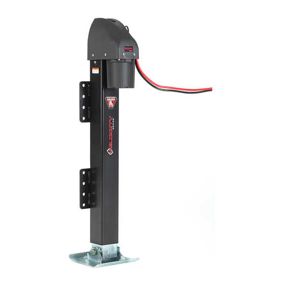
COMPONENTS OF THE JACK:
(Figure A)
A. Manual Override Port
B. Motor Assembly
C. Remote Control Connector Port
D. U-Bolt
E. Mounting Plate
DO NOT
REMOVE SCREW!
1. PREPARE THE TRAILER
Support the trailer by connecting the coupler to the towing vehi-
1.1
cle or by the use of jack stands.
Chock the wheels of the trailer.
1.2
2. MOUNTING THE JACK
When considering the mount location of the jack, be certain to have
adequate ground clearance when fully retracted.
quate ground clearance may result in property damage.
Option 1: The jack must be attached directly to the trailer
2.1
frame with a minimum of four (4) ½" grade 5 fasteners; one fastener
Option 1: Four (4) Bolts
Fig. B
F3920-00 (Rev-B 6923) 3/16
Bulldog
Velocity Series
®
Failure to follow all warnings and instructions may result in product
failure, property damage, serious bodily injury, and/or death.
Installation Instr uctions
A
Fig. A
Inade-
Option 2: Four (4) U-Bolts
Fig. C
• Always replace bent, broken, or worn parts before using this product.
• To avoid accidental shock and/or damage to the electrical system,
disconnect the battery ground cable before installation.
• Secure the load, vehicle and trailer from rolling (by blocking wheels) when
operating jack or coupling trailer.
• These jacks are designed for vertical loading. Excessive side forces may
cause jack failure and must be avoided.
• Do not remove the tamper-resistant screws that secure the motor assembly
to the jack. Removal will cause sudden lowing of the trailer unless
properly supported.
B
in each side of the two mounting plates on the jack (See Figure B).
Torque hardware to 50 ft-lbs.
C
Option 2: The jack must be attached directly to the trailer
frame with a minimum of four (4) U-bolts utilizing a total of eight
holes on the mounting plates; two on the upper section and two on the
lower (See Figure C). Torque hardware to 50 ft-lbs.
On aluminum trailers, it is recommended to use isolation pads
2.2
between the contact points of the jack and trailer (including hardware)
D
to reduce galvanic corrosion.
3. BATTERY CONNECTION
Connect the battery leads directly to the trailer battery: red
3.1
E
lead to the positive terminal post of the battery, black lead to the nega-
tive terminal post of the battery.
provide adequate amperage for this product.
Secure the battery leads with cable-ties, wire loom, etc.
3.2
COMPONENTS OF THE
REMOTE CONTROL: (Figure D)
A. Remote Control
B. Wiring Pigtail
C. Toggle Switch
NOTE: Use silicone-based, dielectric grease on the
connection between the remote and power head.
Jack
™
Vehicle wiring will not
B.
Advertisement
Table of Contents

Subscribe to Our Youtube Channel
Related Manuals for Bulldog Security Velocity Series

Summary of Contents for Bulldog Security Velocity Series
- Page 1 Bulldog Velocity Series Jack ® ™ Read, Understand, Follow and Save These Instr uctions Read, understand and follow all of these instructions and warnings (Instructions) before installing and using this product. Install and use this product only as specified in these instructions. Improper installation or use of this product may result in property damage, serious injury, and/or death. Never allow installation or use of this product by anyone without providing them with these instructions.
- Page 2 Maintenance The Velocity Series™ Jack motor is sealed and maintenance-free. It is important to maintain the electrical system including the battery and charger (not included). Ensure all connections are tight and free of corrosion and that the jack is properly grounded with the coupler (metal-to-metal contact).
- Page 3 Gato Bulldog Velocity Series ® ™ Lea, comprenda, siga y guarde estas instr ucciones Lea, entienda y siga estas instrucciones y advertencias (Instrucciones) antes de instalar y usar este producto. Instale y use este producto únicamente según se espe- cifica en estas instrucciones. La instalación o uso incorrectos de este producto podría resultar en daños a la propiedad, lesiones serias y/o la muerte. Nunca permita que alguien instale o use este producto sin entregarle estas instrucciones.
- Page 4 4. CABLEADO Y CONEXIÓN DEL CONTROL REMOTO Lleve la coleta del cableado del control remoto desde la ubicación deseada hasta el puerto conector ubicado al costado de la cubierta del motor. Conecte firmemente la coleta del control remoto al puerto conector. Asegure la coleta del cableado del control remoto con tiras para amarrar cables, o alambre para garantizar que no haya roce.
- Page 5 Vérin électrique Bulldog Velocity Series ® ™ Veuillez lire, comprendre, observer et conserver ces instructions Il importe de lire, comprendre et observer toutes les instructions et avertissements avant d’installer et utiliser ce produit. Installer et utiliser ce produit uniquement selon les instructions. Une installation ou utilisation inadéquate peut entraîner des dommages à la propriété, des blessures sévères, et/ou le décès. Ne jamais autoriser une personne à...
- Page 6 4. CÂBLAGE ET BRANCHEMENT DE LA TÉLÉCOMMANDE Acheminez le pigtail de la télécommande depuis l'emplacement de votre choix jusqu'à la fiche de connexion située sur le côté du couvercle du moteur. Branchez fermement le pigtail de la télécommande à la fiche de connexion. Fixez le pigtail de la télécommande avec des colliers de serrage, une gaine, etc.
Need help?
Do you have a question about the Velocity Series and is the answer not in the manual?
Questions and answers