Table of Contents
Advertisement
Advertisement
Table of Contents

Subscribe to Our Youtube Channel
Summary of Contents for evenes Gelbi D 4.2
- Page 1 Operating manual and assembly Air / Water Heat Pump Version: 4_07_2020...
-
Page 3: Table Of Contents
1. Description of the Heat Pump ..........................4 2. Construction of the Heat Pump .......................... 4 3. Installing of the Heat Pump ..........................4 4. Description of controller functions ........................8 5. Main menu ................................9 6. Fitters menu ..............................11 7. -
Page 4: Description Of The Heat Pump
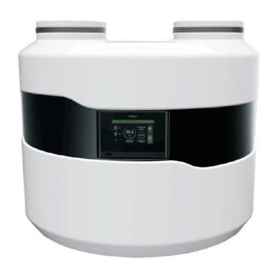
1. Description of the Heat Pump Heat pump GELBI D4.2 is a device designed for preparation domestic hot water. It uses the rotary screw compressor optimised for high condensation temperatures, i.e. enabling heating to high temperature. The air flow is forced via the finned coil by modern, powerful and energy efficient fan. Water is heated in the SWEP plate exchanger made of stainless steel. - Page 5 Keep a distance from the barriers (ceiling walls, etc.) for trouble-free maintenance of the heat pump. In the bottom part of the heat pump housing there is a condensate drain connection to which the drain hose must be connected. It is recommended to drain the condensate into the sewage system and to use a siphon.
- Page 6 Air extracted from one room and exhausted to Air extracted from one room and exhausted another room through the wall to another room Air extracted from the outside through the wall Air extracted from the outside through the wall and exhausted to the outside through the wall and exhausted to the outside through the roof Separation of inlet and exhaust air Heat pump cooperating with recuperator...
- Page 7 The heat pump and the recuperative unit operate independently of each other, therefore the ventilation ducts should also be separated. This means that when the recuperation is working and the heat pump is stopped, then the air flows easily to the ventilation outlet and not to the heat pump.
-
Page 8: Description Of Controller Functions
4. Description of controller functions Description of icons displayed in the controller in the operating mode: 1- Operating mode additional 9- Active weekly schedule of the DHW contact: 10- Active weekly schedule of buffer heating Active controller lock 12- ECO / ECO PLUS mode Active SG End of Heating option... -
Page 9: Main Menu
pump and fan – delay compressor parameter. The electric heater operates above ECO-PLUS temperature, in Party mode and in case of failure. Attention: The heater is not installed in the device. It is an optional external component, which can be controlled by the heat pump controller. 5. - Page 10 5.4 Security 5.4.1 Security active Driver blocks access to functions in the controller menu after a defined period of inactivity. Prevents setting changes by unauthorized persons or children. 5.4.2 Security delay If the option Security active is selected, the controller blocks access to the functions of controller menu after a specified period of inactivity (setting security delay).
-
Page 11: Fitters Menu
6. Fitters menu 6.1 DHW tank set. temperature This function is used to set the tank set-point temperature. The fan, compressor and pump run until the set tank temperature is reached. 6.2 DHW anti-freeze Tank anti-freeze function. It is also active in "standby" mode. 6.2.1 Anti-freeze heating source The user selects the device (heater, heat pump) that will start to protect the tank from freezing. - Page 12 6.3. 1 Anti-freeze threshold When the temperature drops below a certain temperature threshold (factory set limit is 5°C) the heat pump or the electric heater starts permanently. It is switched off when the tank temperature is 3°C higher than the set parameter. 6.4 Schedule When the weekly control function is activated, the heat pump will operate at the set times in comfort mode and the rest in reduced mode.
- Page 13 6.4.4 Temp. reduced The user sets the reduced temperature that the controller will maintain when it is active in the weekly program. 6.5 Circulation pump This function is used to activate the connected circulation pump and to define individual settings. The circulation pump operates in intermittent mode according to the parameters of operating time, break time and weekly schedule.
- Page 14 Temp. reduced- setting the reduced temperature in the buffer tank. 6.8 Ethernet module NOTE This type of control is possible exclusively after purchasing and connecting to the driver the additional ST-505 module which isn't attached to the standard driver. An internet module is a device allowing remote control of the heat pump through the Internet or the local network.
-
Page 15: Service Menu
7. Service menu To open the service menu of the controller, enter a four-digit access code. 7.1 Manual operation The function allows to enable individual devices regardless to other to verify its operation. Press the appropriate icon to switch on each device. - Page 16 7.2 LEGIONELLA settings LEGIONELLA function is used to disinfect the tank. In the service menu the user can configure individual parameters of this function. 7.2.1 LEGIONELLA function temp. The function allows to define the set-point temperature of disinfection. 7.2.2 LEGIONELLA function day Select the day of the week on which the Legionella function will be executed.
- Page 17 7.4 Alarms sound Option to enable/disable the alarm signal. 7.5 Pump anti-stop Function to prevent " stagnation " of the built-in circulation pump. The function also works in "standby" mode. The controller will start the circulation pump according to the following parameters.
- Page 18 Example: when the minimum operating temperature is set to 5°C and the hysteresis is set at 2°C, the heat pump activates at 5°C, but when the temperature drops to 3°C the unit is deactivated. 7.10 Heater operation below min. operation temp. Activates the operation of the heater if the outside temperature is lower than the value set in parameter 7.8 Minimum operating temperature.
-
Page 19: Standby Mode
7.18 Compressor stopping time This parameter prevents too frequent switching on of the compressor at short intervals. 7.19 Flow rate The data set in the parameter "flow" is for information purposes only. 7.20 Erase control temp. alarm This parameter is used for information displayed in driver statistics. The statistics function is available for controllers with energy counting function. -
Page 20: Security And Alarms
9. Security and Alarms To ensure maximum safe and trouble-free operation, the heat pump is protected by automatic reset pressure switches installed in the refrigeration circuit on the low and high pressure sides. The pressure switches are connected to the controller. If any of the pressure switches are triggered, the heat pump operation will be stopped and an acoustic signal will sound. - Page 21 temperature exceeded. - Too high temperature of the - Provide air at a lower notification: suction air temperature control temperature too - Polluted evaporator - Clean the evaporator high AGGREGATE - Dirty filter in the intake air duct -Clean or replace the suction air FALIURE filter.
-
Page 22: Maintenance
10. Maintenance Before and during the heating season check the technical condition of the controller wiring. Check also the controller mounting, clean the dust and other pollutants. User of device is requested to make service activities least once every year, which include for example: •... -
Page 23: Electrical Diagram
PS – Power supply ~230V; W- Fan; K- compressor; H- heater; P1- tank pump; P2- D.H.W. circulation pump, Z1- reversing valve, Z2*- Buffer switch valve (only available for Drops D4.2/Gelbi D4.2 pump model) - Page 24 13.2. Connection of sensors...
-
Page 25: Hydraulic Diagrams
14. Hydraulic diagrams 14.1 Diagram no 1... - Page 26 14.2 Diagram no 2...
- Page 27 14.3 Diagram no 3...
-
Page 28: Technical Data
15. Technical data Scope External temperature °C min: +5 /max 43 The temperature of hot water with the heat pump °C max 60 The temperature of the hot water with the electrical °C heater. Minimum assembly area Heat transfer fluid Water or water and glycol mix Electrical parameters Electrical power supply... - Page 29 The producer is not bearing any responsibility for the malfunction or damage to the resulted from the heat pump incorrect selection capacity of the tank. Concludes fluorinated the greenhouse gases overcame by protocol with Kyoto. The used product cannot be treated as communal scraps. Dismounted, equipment is necessary to deliver to the point of the gathering of electric equipment and electronic for the purpose of recycling.
-
Page 30: Start-Up Protocol Of The Heat Pump Gelbi D4.2
Start-up protocol of the heat pump GELBI D4.2 Copy for the Investor Device serial number Name and address of the Investor Name surname commissioning person Place of installation (e.g. basement) Air ducts Diameter: Material: Heating pipeline Diameter: Material: Heating diagram corresponding with Diagram no: Other: the operating instructions... -
Page 31: Start-Up Protocol Of The Heat Pump Gelbi D4.2
Start-up protocol of the heat pump GELBI D4.2 Copy for the Manufacturer Device serial number Name and address of the Investor Name surname commissioning person Place of installation (e.g. basement) Air ducts Diameter: Material: Heating pipeline Diameter: Material: Heating diagram corresponding with Diagram no: Other: the operating instructions... - Page 32 In case of malfunction of the heat pump “The start-up protocol” is attached to the complaint notification, to be sent to the manufacturer. The Protocol is the basis for defining the correctness of the selection and installation method of the device.
Need help?
Do you have a question about the Gelbi D 4.2 and is the answer not in the manual?
Questions and answers