Table of Contents
Advertisement
Advertisement
Table of Contents

Related Manuals for Datacom DM4380


Summary of Contents for Datacom DM4380
- Page 1 DM4380 CARRIER ETHERNET SWITCH INSTALLATION GUIDE 204.4336.00 – October/2019...
-
Page 2: Legal Note
In spite the fact that all the precautions were taken in development of the present document, DATACOM shall not be held responsible for eventual errors or omissions as well as no obligation is assumed due to damages resulting from the use of the information included in this guide. -
Page 3: Contacts
DM4380 – Installation Guide Contacts CONTACTS ECHNICAL UPPORT Datacom has available a support portal - DmSupport, to help the customers in use and config of our equipment. Access DmSupport made through link: https://supportcenter.datacom.com.br In this site the following are available: firmwares, technical datasheets, config guide, MIBs and manuals for download. -
Page 4: Product Documentation
DM4380 – Installation Guide Product Documentation PRODUCT DOCUMENTATION BOUT THIS OCUMENT This document is part of a set of documents prepared to provide all necessary information about DATACOM products. OFTWARE LATFORM – UICK ONFIGURATION UIDE Provides instructions on how to set the functionalities in a quick manner in the equipment –... -
Page 5: Table Of Contents
DM4380 – Installation Guide Contents CONTENTS LEGAL NOTE ....................................2 WARRANTY ....................................2 CONTACTS ....................................3 ..............................3 ECHNICAL UPPORT ..............................3 ENERAL NFORMATION PRODUCT DOCUMENTATION ..............................4 ............................... 4 BOUT THIS OCUMENT ..............................4 OFTWARE LATFORM ..............................4 ARDWARE LATFORM CONTENTS .................................... - Page 6 DM4380 – Installation Guide Contents ..................24 ONNECTING THE PROTECTIVE GROUNDING ..............................24 ENTILATION ........................25 OWERING THE QUIPMENT ’ ....................25 HECKING THE PRODUCT S OPERATION INSTALLING AND REMOVING QSFP28/QSFP+/SFP/SFP+ MODULES............. 27 SFP+/SFP M ....................27 NSTALLING THE ODULES SFP+/SFP M ......................
-
Page 7: Introducing The Hardware Installation Guide
UIDE This guide provides information about hardware specification and installation procedures from DM4380 carrier ethernet switch family. This document also covers initial configuration, those normally needed after hardware installation. It is assumed that the individual or individuals managing any aspect of this product have basic understanding of Ethernet and Telecommunications networks. - Page 8 DM4380 – Installation Guide Introducing the Hardware Installation Guide WEEE Directive Symbol (Applicable in the European Union and other European countries with separate collection systems).This symbol on the product or its packaging indicates that this product must not be disposed of with other waste.
-
Page 9: Getting Started
Before connecting any cable to the equipment, make sure that the grounding system is functional. Optical Transceivers used in DM4380 have invisible LASER emitting. Although all DATACOM homologated transceivers and most of the market transceivers comply with LASER safety standards, avoid direct contact and exposure to eyes and skin. -
Page 10: Hardware Description
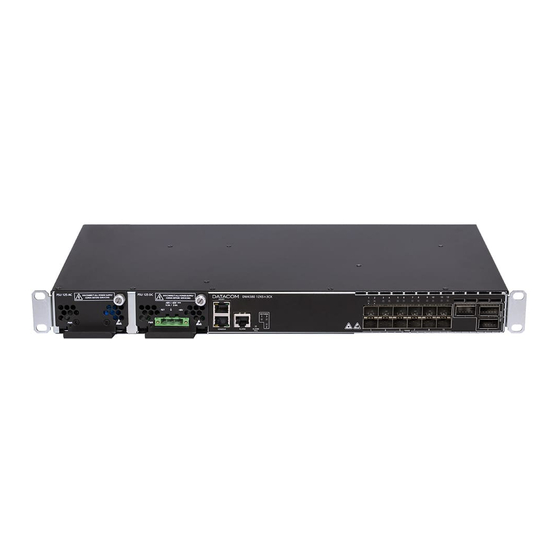
Hardware DESCRIPTION 3 HARDWARE DESCRIPTION This chapter describes the DM4380 line hardware features. 3.1 P RODUCT OVERVIEW The DM4380 line has the product version shown below. Figure 1 - DM4380 12XS+3CX 3.2 M DM4380 12XS+3CX ODEL Figure 2 - DM4380 12CX+3CX Views... -
Page 11: Equipment Status Leds
3.3 E QUIPMENT STATUS The DM4380 Switch has two statuses indicating LEDs in the front panel, the LED ALARM/FAIL located in the Mainboard and the LED PWR located in each PSU. The table below describes the behavior of the status LEDs of the equipment. -
Page 12: Usb Interface Console
Reserved Reserved Table 3 - Console interface connector pin assignment 3.5 USB I NTERFACE ONSOLE For management via USB, the DM4380 has a USB console port accessible via Mini-USB cable (not included) on rear panel. driver this interface Windows found http://www.datacom.com.br/support. -
Page 13: Data Interface
3.8 D NTERFACE 3.8.1 10 Gigabit SFP+ Optical Ethernet Interfaces (10GBase-X) The DM4380 12XS+3CX has 12 10 Gigabit Optical Ethernet interfaces using SFP+ connectors. The status indicating LED contains the LINK/ACT/SPEED information on the same bicolor LED. 204.4336.00 - October/2019... - Page 14 Data sending and/or receiving activity Blinking YELLOW Link Down (active port) Table 5 - 10GE SFP+ Interface LED indicators 3.8.1.2 40 and 100 Gigabit Optical Ethernet Interfaces The DM4380 12XS+3CX has 3 high-speed interfaces using QSFP28 connectors. 204.4336.00 - October/2019...
- Page 15 DM4380 – Installation Guide Hardware DESCRIPTION Figure 7 – 40/100GE Ports 3.8.1.3 40 and 100 Gigabit Optical Ethernet Interface LED indicators The 40GE/100GE ports have LEDs that indicate the operation of the ports on the left front part of the equipment, as shown in figure 8. The convention to indicate the operation and the 40GE and 100GE interface operating mode is described in Table Figure 8 –...
-
Page 16: Larm Input And Output
3.9 A LARM INPUT AND OUTPUT The DM4380 has two alarm inputs and one alarm output in an RJ45 connector. Alarm 1 and 2 inputs are isolated via optocoupler. External alarm detection occurs when the voltage difference between IN+ and IN- reaches 12V. The Table 7 presents the voltages and status for alarm 1 and 2 inputs. - Page 17 DM4380 – Installation Guide Hardware DESCRIPTION The PSU 125 AC has three-pin IEC 320/C14 plug power terminals located in rear panel of the equipment. The PSU 125 power supplies operate in a 1:1 redundancy manner, with only one being sufficient to maintain full operation of the equipment. The combination of AC and DC power supplies in the same equipment is allowed.
- Page 18 DM4380 – Installation Guide Hardware DESCRIPTION In the PSU 125 AC, fuse F1 supports currents of up to 5A. They are of Fast Acting type, 250V. If necessary, only replace it with one of the same specifications. The F1000 supports up to 15A. It is a Fast output fuse Acting type, 86V.
- Page 19 DM4380 – Installation Guide Hardware DESCRIPTION 3.10.1.2 PSU 125 DC The figure below shows the pin settings of the TERMINAL BLOCK connector to power the switch. Figure 12 - DC Power Connector Pinout Settings 3.10.2 Power Cables 3.10.2.1 PSU 125 AC...
- Page 20 DM4380 – Installation Guide Hardware DESCRIPTION Figure 13 – Removing the TERMINAL BLOCK from the PSU 125 DC Locate the power cord shipped with the PSU 125 DC, and cut it to Step 2 the desired preferred length. If the cable needs to be replaced, it is...
-
Page 21: Protective Grounding
Hardware DESCRIPTION 3.11 P ROTECTIVE ROUNDING The DM4380 equipment has a Protective Ground point on the rear panel. This connector must be connected to the installation ground (FGND) as instructed in the DM4380 Installation chapter. Figure 16 – Protective Grounding DM4380 12XS+3CX... -
Page 22: Dm4380 Installation
4.2 I DENTIFYING THE PRODUCT Make sure that the product received matches the figures in this guide. The DM4380 has a label on the rear side of the mechanics. It contains model information, product code and serial number. Check if there is any divergent information on the label regarding the information on the packaging. -
Page 23: 19- Inch Rack Installation
4.4 19- INCH RACK INSTALLATION The DM4380 was designed to be installed to 19-inch racks, occupying only 1U in height. To choose the suitable installation site, pay attention to the following items: Choose an easily accessible location where your LEDs can be viewed;... -
Page 24: Connecting The Protective Grounding
DM4380 Installation 4.5 C ONNECTING THE PROTECTIVE GROUNDING The DM4380 has a place on its rear panel to attach a cable to connect the Protective Grounding. The grounding cable is not part of the basic accessories shipped with the switch. The cable indicated for the installation must have a thickness of 10 to 12 AWG. -
Page 25: Owering The Quipment
’ HECKING THE PRODUCT S OPERATION Considering that the DM4380 was installed according to the guidelines in this guide, the steps below indicate whether the equipment is operating normally. Immediately after the unit is powered by either of the power Step 1 inputs, the power-on PSU PWR indicator will light up. - Page 26 DM4380 – Installation Guide DM4380 Installation Once the startup process has been successfully completed, the operator must configure the equipment management as indicated in the Logging in for First Time section. 204.4336.00 - October/2019...
-
Page 27: Installing And Removing Qsfp28/Qsfp+/Sfp/Sfp+ Modules
This chapter describes how SFP/SFP+/QSFP+/QSFP28 transceivers must be installed and removed. It also informs about DATACOM guidelines for the cleaning and storage of modules and optical fibers. SFP (Small Form-factor Pluggable), SFP+, QSFP+ and QSFP28 transceivers are inserted into the switch's SFP, SFP+, QSFP+ and QSFP28 ports, operating as transceivers between the switch and the selected optical communication path. - Page 28 Table 12 – Inserting a SFP/SFP+ The DM4380 equipments are sent with dust cover plugs in all SFP/SFP+ ports. Before to insert a transceiver in a port, remove the dust cover. Ports without installed transceivers should keep dust cover protection to avoid electrical connections free of dust.
-
Page 29: Removing Sfp+/Sfp Modules
Installing and Removing DM4380 – Installation Guide QSFP28/QSFP+/SFP/SFP+ Modules 5.2 R SFP+/SFP M EMOVING ODULES To remove the modules, simply follow the installation instructions in reverse order. Follow the same procedure for copper SFP and copper SFP+ Twin-Ax cables: Remove the optical cables. -
Page 30: Removing Qsfp28/Qsfp+ Modules
Table 14 – Inserting a QSFP28/QSFP+ The DM4380 equipments are sent with dust cover plugs in all QSFP28/QSFP+ ports. Before to insert a transceiver in a port, remove the dust cover. Ports without installed transceivers should keep dust cover protection to avoid electrical connections free of dust. - Page 31 Installing and Removing DM4380 – Installation Guide QSFP28/QSFP+/SFP/SFP+ Modules When DM4380 operates over 45ºC ambient temperature recommended to use only QSFP+/QSFP28 industrial temperature class transceivers. Contact the Technical Support for any doubt. 204.4336.00 - October/2019...
-
Page 32: Logging In For First Time
SSH connection from a remote management terminal. To do this, just plug a compatible console cable and run a terminal emulator as Hyper Terminal or any other similar using a computer or laptop. The default configuration for DM4380 is baud rate 9600, with 1 stop bit and no parity, following below figure. -
Page 33: Configuring Users
Command Line Interface (CLI). The CLI is accessed by using a direct or USB console connection or by using a SSH or Telnet connection from a remote management terminal. Only one account is pre-configured in default factory config in the DM4380 line: admin User Password... -
Page 34: Changing Default Administrator Account Password
DM4380 – Installation Guide Logging in for First Time 6.4 C HANGING EFAULT DMINISTRATOR CCOUNT ASSWORD For security reasons it is highly recommended to modify the default administrator account password. Entering the configuration mode: Step 1 # configure Entering the user mode:... -
Page 35: Technical Specification
(Watts) PSU 125 AC 150W PSU 125 DC 3.3A Maximum Current (Amperes) PSU 125 AC 1.66A Table 22 – DM4380 Power Consumption 7.3 P HYSICAL PECIFICATIONS DM4380 12XS+3CX Height 44 mm Width (with brackets) 482 mm Width (without L brackets) -
Page 36: Nvironment Nformation
DM4380 12XS+3CX Operation Temperature 0°C to 55°C Operation Relative Humidity 10% to 90%, non-condensing Operating Altitude 0 to 3000m Storage Temperature -20°C to 70°C Table 24 – DM4380 – Environment Information When DM4380 operates over 45ºC ambient temperature recommended only... -
Page 37: Standards And Regulations
Environmental Conditions for storage Class 1.2 019-1-2, Environmental Conditions for Transport Class 2.3 Table 25 – DM4380 – Standards and Regulations Rua América, 1000 | 92990-000 | Eldorado do Sul | RS | Brasil +55 51 3933 3000 sales@datacom.com.br 204.4336.00 - October/2019...
Need help?
Do you have a question about the DM4380 and is the answer not in the manual?
Questions and answers