Advertisement
Table of Contents
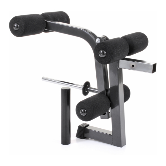
Ironmaster Leg Attachment for SuperBench
Congratulations on your purchase of this fine Ironmaster product. Be sure to read and
understand the operating instructions to achieve the best performance and avoid injury.
CAUTION: The IRONMASTER LEG ATTACHMENT CAN ONLY BE SAFELY USED WITH THE IRONMASTER SU-
PER BENCH: Ironmaster assumes no liablity if used with any other product other than the IRONMASTER SUPER-
BENCH. Follow all assembly instructions and refer to the exploded diagram on the back side of this page.
CONTENTS:
Part #
Part Name
1
Stub Frame
2
End Cap
3
Leg Frame
4
Plug
5
Plug
6
Adaptor
7
Plug
8
Screw
10
Axle
11
Washer
12
Bolt
13
Roll Pad Tube
14
Roller Pad
15
M8 Washer
16
Cap
17
Bolt
19
Allen Wrench
20
Allen Wrench
22
Bolt
23
Cap Nut
Congratulations on your purchase of this fine Ironmaster product. The following instructions will help you assemble the
unit and provide some details on use as well. The only tools required are two adjustable wrenches and a 6mm Allen
Wrench (Included with Hardware kit). Check prior to Assembly that parts from both the main box and hardware kit are
all present.
Warranty Information:
Ironmaster warrants to the original purchaser that this Home Fitness Product will be free from defects in workmanship and materials for a specific period from date of purchase based on the part type
listed below. During the warranty period, Ironmaster will either repair or replace, at its option, defective part(s) at no charge. Warranty covers in home use only.
1 year for normal wear items such as rubber, upholstered parts and surface finishes.
10 years for frame and structural components.
Shipping costs are not included in the warranty and some items may need to be sent to Ironmaster for repair or replacement. Installation of any parts and labor involved is not included. The warranties
described above shall be the sole and exclusive remedy available to the purchaser. Correction of defects, in the manner and for the period of time described above, shall constitute complete fulfill-
ment of all liabilities and responsibilities of Ironmaster to the purchaser with respect to the product, and shall constitute full satisfaction of all claims, whether based on contract, negligence, strict
liability or otherwise. In no event shall Ironmaster be liable or in any other way responsible for damages or defects in the product which were caused by repairs or attempted repairs performed by
anyone other than Ironmaster or Authorized service Contractor. This warranty shall not apply if the defect was caused by misuse, neglect or normal wear and tear of the product purchased. Nor shall
Ironmaster be liable or in any way responsible for any incidental or consequential economic or property damage. Some states do not allow the exclusion of incidental or consequential damage, so the
above exclusion may not apply to you.
Assembly & Operating Instructions
Description
Square tube with brackets and stub that plugs into the bench
Rubber foot cap *already installed*
Square tube bent with plate holder
Square 45 x 45 mm *already installed*
Diameter 1" *already installed*
Olympic Plate Adapter Sleeve
Black plastic cap for Olympic Adapter *already installed*
M6 x 8 mm (Allen Head)
Diameter 20mm x 49.5 mm
O.D. 20 mm x I.D. 10 mm
M10 x 20 mm
Diameter 1.0" x 400 mm
Diameter 4" x 7" (L)
Chrome
Black plastic dome cap
M8 x 25 mm (Allen Head)
M6
M8
M10 x 70mm bolt
M10 cap nut
Qty
1
1
1
2
1
1
1
1
1
5
3
3
6
6
6
6
1
1
1
1
Advertisement
Table of Contents

Subscribe to Our Youtube Channel
Related Manuals for Ironmaster Leg Attachment for SuperBench


Summary of Contents for Ironmaster Leg Attachment for SuperBench
- Page 1 10 years for frame and structural components. Shipping costs are not included in the warranty and some items may need to be sent to Ironmaster for repair or replacement. Installation of any parts and labor involved is not included. The warranties described above shall be the sole and exclusive remedy available to the purchaser.
- Page 2 ASSEMBLY Steps: To assemble the attachment, first unpack all components and locate the hardware kit. Assemble the Leg Frame (#3) to the Stub Frame (#1). Insert the Axle #10 into the bushing housing and bolt together using bolt #22, washers #11 and cap nut #23. Insert the 3 roll pad tubes #13 in the frame and stub locations and bolt them in place with bolt #12 and washers #11.
Need help?
Do you have a question about the Leg Attachment for SuperBench and is the answer not in the manual?
Questions and answers