Advertisement
Quick Links
Advertisement

Related Manuals for ESX VISION NAVICEIVER


Summary of Contents for ESX VISION NAVICEIVER
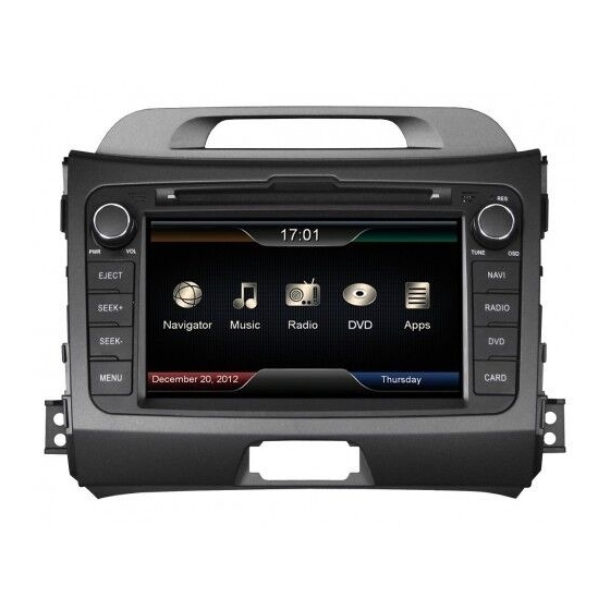
- Page 1 VN710 KI-SPORTAGE...
- Page 2 INSTALLATION NOTES / Installationshinweise Important Notes prior to installation: This guide is an installation aid for a proper installation of the device. Please read the following instructions prior installation: 1.) Please treat all parts of the sound system and the components of your vehicle with caution. 2.) Follow under all circumstance the regulations of the vehicle manufacturer and do not make any modifications on the vehicle, which could interfere the driving safety.
-
Page 3: Table Of Contents
INDEX / Inhaltsverzeichnis Scope of delivery ..........................4 Lieferumfang ............................4 Connection Diagram ........................... 6 Anschlussdiagramm ..........................6 Installation notes ..........................7 Installationshinweise..........................7 Installation example ........................... 9 Einbaubeispiel ............................9... -
Page 4: Scope Of Delivery
SCOPE OF DELIVERY / Lieferumfang ITEM FIGURE SLOT QUANTITY Artikel Abbildung Steckplatz Anzahl Main DeviCe & PaneL – Hauptgerät & Blende STYLUS – Markierstift MiCRO SD CaRD 8GB inKL: naviGaTiOn SOFTWaRe – MicroSD Speicherkarte 8GB Navigationssoftware ReMOTe COnTROL – Fernbedienung viDeO inPUT CaBLe SeT Video-Eingang Kabelsatz ReaR CaM inPUT... -
Page 5: Lieferumfang
SCOPE OF DELIVERY / Lieferumfang ITEM FIGURE SLOT QUANTITY Artikel Abbildung Steckplatz Anzahl aUDiO OUT (SUBWOOFeR/CenTeR) Audio-Ausgang (Subwoofer/Center) USB CaBLe SeT WiTH 1 COnneCTOR USB Kabelsatz mit 1 Anschluß iPOD / iPHOne COnneCTOR iPod / iPhone Anschluss BT-MiCROPHOne BT-Mikrofon GPS anTenna GPS Antenne HanDBRaKe COnneCTiOn Handbremsen-Anschluss... -
Page 6: Connection Diagram
CONNECTION DIAGRAM / Anschlussdiagramm BT-MiCROPHOne BT-Mikrofon aUDiO OUT (DUaL ZOne) Audio-Ausgang (Dual Zone) aUDiO OUT (SUBWOOFeR/CenTeR) Audio-Ausgang (Subwoofer/Center) viDeO inPUT CaBLe SeT Video-Eingang Kabelsatz FROnT CaM inPUT (optional) Frontkamera-Eingang (optional) SPeCiFiC COnneCTORS OF THe veHiCLe Fahrzeugspezifische Stecker WiTHOUT FUnCTiOn aM/FM anTenna Ohne Funktion AM/FM Antenne GPS anTenna... -
Page 7: Installation Notes
Vermeiden Sie das Verlegen des Kabels über die Lenksäule. In der Regel sollte das Kabel lang genug sein, um die A-Säule (Fahrerseite) über die Beifahrerseite zu erreichen. Ein evtl. werksseitig vorhandenes Mik- rofon ist nicht kompatibel mit dem ESX Gerät. Bitte verwenden Sie das mit- gelieferte Mikrofon. -
Page 8: Installationshinweise
INSTALLATION NOTES / Installationshinweise Handbrake connection: Connect the cable from the handbrake connection (14) with the handbrake signal in your vehicle. The signal must be connected with ground while the handbrake is applied. Please contact for a proper and safe installation your car dealer! according to legal regulations, the device must playback a DvD or video on the main screen only with the handbrake applied, never connect the cable permanently with the vehicle‘s ground. -
Page 9: Installation Example
INSTALLATION EXAMPLE / Einbaubeispiel 1.) First remove the screws on the side panels. (below the original radio). 1.) Entfernen Sie die beiden Schrauben an den Seitenblenden (unterhalb vom Original-Radio). 2.) Loosen therefor the cover with a screwdriver to reach the screws. 2.) Lockern Sie dafür die Abdeckung mit einem Schraubendreher um an die Schrauben zu gelangen. -
Page 10: Einbaubeispiel
INSTALLATION EXAMPLE / Einbaubeispiel 5.) Remove the left screw (each side 1) of the radio panel (Phillips screw). 5.) Entfernen Sie linke Schraube (pro Seite 1) der Blende (Kreuzschlitz). 6.) Remove the right screw (each side 1) of the radio panel (Phillips screw). 6.) Entfernen Sie rechte Schraube (pro Seite 1) der Blende (Kreuzschlitz). - Page 11 Sie alle Kabelstecker auf der Rückseite. 10.) Remove the metal mounting brackets on the original radio and mount them accordingly to the new eSX device. 10.) Entfernen Sie die Metallhalterungen am Original-Radio und befestigen diese entsprechend am neuen ESX Gerät.
- Page 12 15.) Unlock the warning light switch from the original radio panel and attach it at the enclosed panel from the eSX device. 15.) Entrasten Sie den Warnblinkschalter an der originalen Radioblende und befestigen diesen an der mitgelieferten Blende des ESX Geräts.
- Page 13 Achten Sie darauf, dass die Plastikhalterungen von Bild 17 einrasten. 19. Before you complete the installation of the new eSX device, check its function. Please note that it may take up to 15 minutes, until a GPS signal can be received (in the open).
- Page 14 NOTES / Notizen...
- Page 15 NOTES / Notizen...
- Page 16 Car Media Systems · audio Design GmbH am Breilingsweg 3 · D-76709 Kronau/Germany Tel. +49(0)7253 - 9465-0 · Fax +49(0)7253 - 946510 www.esxaudio.de - www.audiodesign.de ©2013 all Rights Reserved...
Need help?
Do you have a question about the VISION NAVICEIVER and is the answer not in the manual?
Questions and answers