Table of Contents
Advertisement
Advertisement
Table of Contents

Related Manuals for Spaceman 6224


Summary of Contents for Spaceman 6224
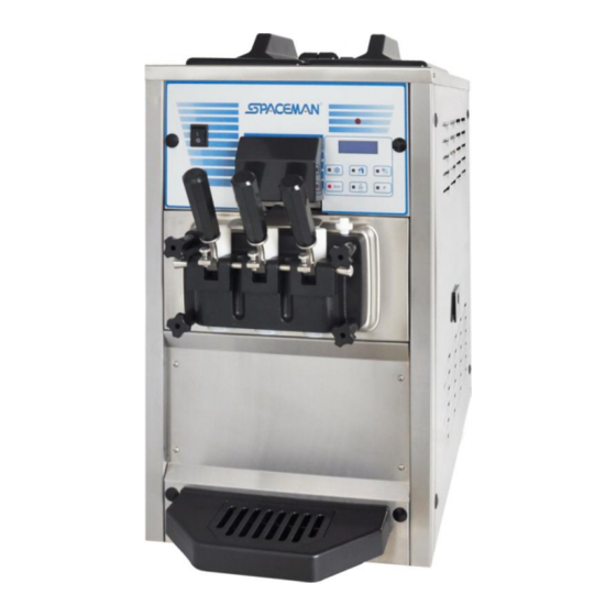
- Page 1 OPERATOR’S MANUAL Model: 6224 www.spaceman-company.com...
-
Page 2: Table Of Contents
Table of Contents Section1 To the installer ----------------------------------------------------- Air Cooled Units -------------------------------------------------------------------- 1 Electrical Hook-Up Installation For 220V/ 50Hz/ 1Ph, Supplied With Cord and Plug --------------------------------------------------- Specification ------------------------------------------------------------------------ Section2 To the Operator -------------------------------------------------- Section3 Safety ---------------------------------------------------------------- Section4 Installation Instructions ----------------------------------------- Section5 Important: Operating Control -------------------------------... - Page 3 Section8 Troubleshooting Guide --------------------------------------- 26 Section9 Electrical Drawing ---------------------------------------------- 28 Note: Continuing research results in steady improvements; therefore, information in this manual is subject to change without notice.
-
Page 4: To The Installer
To the installer Air Cooled Units The model 6224 ice cream machine’s air cooling unit requires a minimum of 15.2cm of clearance around both sides. Install the skirt provided on the right side of the unit and place the back of the unit against a wall to prevent recirculation of warm air. - Page 5 Page2 Section1 To the installer ELECTRICAL: Voltage AC: 1 Phase 200-240V 50 Hertz Total Run Amps: 12 Amps Drive Motors: 1.5 HP Main Compressor: 3150 BTU/Hr. (BTU may vary depending on compressor used.) COOLING Air-cooled required minimum 15.2cm air clearance around the freezer. HOPPER Two hoppers, 8 liters×2, refrigerated and insulated.
-
Page 6: Section2
This Operator’s Manual should be read before operating or performing any maintenance on your equipment. The Models 6224 will NOT eventually compensate and correct for any errors during the set-up or filling operations. Thus, the initial assembly and priming procedures are of extreme importance. -
Page 7: Section3
Section3 Safety We at Spaceman Company are concerned about the safety of the operator when he or she comes in contact with the freezer and its parts. Spaceman has gone to extreme efforts to design and manufacture built-in safety features to protect both you and service technician. -
Page 8: Section4
Page 5 Section4 Installation Instructions Caution Failure to install the freezer within recommended limits will result in poor performance of this system, premature component failure and cancellation of the warranty. Installation of freezer involves moving the unit close to its permanent location, removing all protective packaging, setting in place and cleaning. - Page 9 I. When connect the power supply and press on the ON/OFF switch, the fluorescent display indicate: SPACEMAN MODEL 6224 J. Press STOP button, then press P button indicate temperature of cylinder and hopper. HOPPER TEM. CYCLINDER TEM. 10C IMPORTANT: If one or both of two temperature value(s) indicate(s) “00C”, you must STOP machine...
-
Page 10: Section5
Page 7 Section5 Important: Operating Control Before operating the machine, it is required that the operator know the function of each operating control. Refer to Figure 5-1 Figure 5-2 for location of the controls panel of the machine. It is easy to activate and control all of the machine functions from the front panel. -
Page 11: Symbol Definitions
Important: Operating Control Symbol Definitions To better communicate in the International arena, symbols have replaced words on many of our operator switches. SPACEMAN equipment is designed with these International symbols. The following chart identifies the symbol definitions. R E S E T... -
Page 12: Wash Button
Page 9 Section5 Important: Operating Control WASH BUTTON (Item 2) 1. Press WASH button, the led of WASH comes “ON”. The beater motor operate, fluorescent display indicates “WASHING”. 2. Press P button, the fluorescent display indicates: Indicate present temperature of mix in hopper. HOPPER 0.0C CYCLINDER... -
Page 13: Standby Button
Page10 Section5 Important: Operating Control 5. Press P button once again, the fluorescent display indicates: Indicate the electric current of beater motor. MOTOR 1.34 / 2.00 A ****************** Indicate the scale of viscosity. When the second line is full by “*”, the product is at serving viscosity. 6. -
Page 14: Ice Cream Button
Page 11 Section5 Important: Operating Control ICE CREAM BUTTON (Item 5) 1. Press ICE CREAM button to check the number of servings dispensed from the machine. The fluorescent display indicates: Indicate the quantity of ice cream serviced today. Today: 00000 Indicate the quantity of ice cream serviced total Total: 0000000... - Page 15 Page12 Section5 Important: Operating Control Press the STANDBY button to increase the value. Press the P button to decrease the value. 2. Press RESET button once, fluorescent display indicates: MIX TEMPERATURE SET: 4.5C In COOL and STANDBY cycle, machine will start to cool mix in hopper when temperature of mix in hopper is 1 degree higher than above value.
-
Page 16: Fault Description
Page 13 Section5 Important: Operating Control 5. Press RESET button once, fluorescent display indicates: ENTER CODE 0 0 0 0 It is requirement of service set pass code 6. Press RESET button, fluorescent display will cycle from step 1. 7. If exit SET MENU not save setting, press WASH button, fluorescent display indicates: STOP NOT SAVE 8. - Page 17 Page14 Section5 Important: Operating Control 2. In COOLING cycle, if fluorescent display appears: STOP 1 LOW TEM. PROTECT The temperature of cylinder achieves or lower than the lowest temperature setting. The led of COOL and STANDBY will be sparked, compressor stop, beater motor working.
- Page 18 Page 15 Section5 Important: Operating Control 5. Reset Button The reset protects the beater motor from an overload condition. If an overload occurs, the reset mechanism will trip. The machine shuts down, it appears no power supply. Firstly find out the reason of protection, solve problem.
-
Page 19: Section6
Page16 Section6 Operating Procedures The machine has been selected to illustrate the pictured step-by-step operating procedures. It has a 1.7liter capacity in freezing cylinder. The mix flows by gravity from the hopper to the freezing cylinder through an air tube. We begin our instructions at the point where we enter the store in the morning and find the parts disassembled and laid out to air dry from the previous night’s cleaning. - Page 20 Page 17 Section6 Operating Procedures 4. Assemble three design caps to the bottom of the dispensing door spout. ITEM Part Number QTY. Description 225206007 Middle Dispensing Valve 225206004 Side Dispensing Valve 225206006 O-ring 225206002 O-O ring 225206005 Dispensing Handle Retention 225206001 Dispensing door 225206008...
-
Page 21: Sanitizing
Page18 Section6 Operating Procedures Sanitizing Step 1 Prepare 3.8 liters of an approved 100PPM sanitizing solution. USE WARM WATER AND FOLLOW THE MANUFACTURER’S SPECIFICATIONS. Step 2 Pour 3.8 liters of sanitizing solution into the hopper and allow it to flow into the freezing cylinder. -
Page 22: Closing Procedure
Page 19 Section6 Operating Procedures Step 2 Install the front drip tray and splash shield under the freezer door. Steps 3 Slide the rear drip into the hole in the side panel. Step 4 With a pail beneath the door spout, raise the draw valve. Fill the mix hopper with FRESH mix and allow it to flow into the freezing cylinder. -
Page 23: Rinsing
Page20 Section6 Operating Procedures Rinsing Step 1 Pour one 3.8 liters of cool, clean water into the mix hopper. With the brushes, scrub the mix hopper, the mix level stem and the mix inlet hole. Step 2 With a pail beneath the door spout, press the Wash Keypad in “On” position and raise the draw valve. -
Page 24: Disassembly
Page 21 Section6 Operating Procedures Disassembly Step 1 BE SURE THE POWER KEYPAD IS IN THE “OFF” POSITION. Step 2 Remove the hand screws and the dispensing door. Remove the beater assembly from the freezing cylinders and take these parts to the sink for cleaning. Step 3 Remove the front drip tray and the splash shield from the freezer. - Page 25 Page22 Section6 Operating Procedures Step 6 Remove the rear drip pan from the side panel and take it to the sink for cleaning. Note: If the drip pan is filled with an excessive amount of mix, this is an indication that the drive shaft O-ring of the beater assembly should be replaced or properly lubricated.
-
Page 26: Section7
Page 23 Section7 Important: Operating Checklist During cleaning and sanitizing Cleaning and sanitizing schedules are governed by your State or local regulatory agencies and must be followed accordingly. The following check points should be stressed during the cleaning and sanitizing operations. WE RECOMMEND DAILY CLEANING AND SANITIZING. - Page 27 Page24 Section7 Important: Operating Checklist Regular Maintenance Checks 1. Check the rear shell bearing for signs of wear (excessive mix leakage in rear drip pan) and be certain it is properly cleaned. 2. Using a screwdriver and cloth towel, keep the rear shell bearing and the female hex drive socket clean and free of lubricant and mix deposits.
- Page 28 Page 25 Section8 Troubleshooting Guide PAGE PROBLEM PROBABLE CAUSE REMEDY REF. a) The mix level is a. Fill the mix hopper with No product inadequate in the mix mix. being hopper. dispensed b) The beater motor b. Reset the freezer. overload.
- Page 29 Page26 Section8 Troubleshooting Guide PAGE PROBLEM PROBABLE CAUSE REMEDY REF. a. Operating freezer a. Install the front bearing The freezing without the front bearing on the freezer door. cylinder walls on the freezer door. are scored. b. The gear unit or the b.
- Page 30 Page 27 Section9 Electrical Drawing Item Part Number QTY. Description Motor – Beater 1100W/60HZ 5001019014 Compressor – Tecumseh CAJ2446 5001009052 5001007003 Fan Motor - Main Compressor – Mix 5001008007 5001004001 Fan Motor - Mix 5002005009 Thermal Overload Relay 5002001005 Contactor of Motor 5002001005 Contactor of Compressor 5002017004...
- Page 31 Page28...
Need help?
Do you have a question about the 6224 and is the answer not in the manual?
Questions and answers
what does motor overload mean