
Related Manuals for Wellis Lipari EE00276


Summary of Contents for Wellis Lipari EE00276
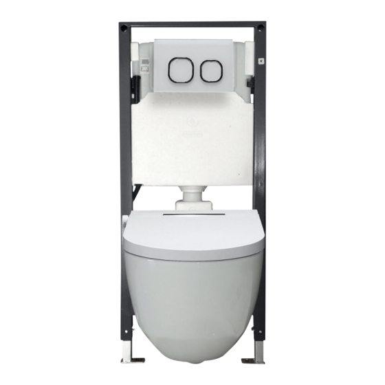
- Page 1 Lipari toilet tank INSTALLATION MANUAL Lipari WC-Tank MONTAGEANLEITUNG Lipari réservoir de toilette MANUEL D’INSTALLATION Lipari wc tartály SZERELÉSI ÚTMUTATÓ EE00276...
- Page 2 1. General dimension and water supply drawing Mounting wall 2. Water supply from back Dimension of H1 & H2 (water supply should be connected subject to available parts. to angle valve inside cistern) Mounting wall 2. Water supply from top Dimension of H1 &...
- Page 3 2. Drill holes on mounting wall and Inward floor and install expansions screw Outward Wall bracket can be mounted inwardly and outwardly. (The hole a distance will be difference) Drill a hole of insert expansion fix the wall → → Ø1 Ox75 screw bracket into wall...
- Page 4 4. Adjustment of socket head screw and floor fixing accessories Washer Optional inward or outward installation of adjusting leg Move adjusting leg to de- sired position. Water 5. Adjustment and fixation of mounting frame supply Angle valve Pretighten the nut and when frame location is seated, lock the nut.
- Page 5 6. Mounting of installation accessories Small plugging tube (to reserve space for flush- ing piping and wall building. Protective cover (to protect con- necting screw at wall building Big plugging tube Finished assembly drawing. Connecting screw (to reserve space for (to mount ceramic bowl) discharging piping at wall building)
- Page 6 8. Mounting of ceramic bowl Fully insert the straight tube into Apply lubricant on rubber washers cistern flushing outlet and connect- of straight tube and connecting pipe, ing pipe into discharging outlet. Dawn the lines as above picture. then insert into ceramic holes. As per drawing, L1 is distance between the two lines on straight tube.
- Page 7 1. Allgemeine Abmessungen und Zeichnung der Wasserversorgung Montagewand 2. Wasserversorgung von oben. Abmessungen für H1 und H2 (Wasserversorgung sollte an Eckventil vorbehaltlich verfügbarer Teile. im Spülkasten angeschlossen werden) Montagewand 2. Wasserversorgung von hinten: Abmessungen für H1 und H2 (Wasserversorgung sollte an Eckventil vorbehaltlich verfügbarer Teile.
- Page 8 2. Bohren Sie Löcher in die Wand (Nach innen) und Boden und installieren Sie (Nach außen) Wandhalterung kann nach innen und außen montiert werden. (Der Abstand Loch A stellt die Differenz dar) Bohren Sie ein Setzen Sie die Befestigen Sie die →...
- Page 9 4. Einstellung der Inbusschraube und des Bodenbefestigungszubehörs Scheibe Wahlweise nach innen oder außen liegender Einbau des Einstellfußes Einstellfuß in die gewünschte Position bringen Wasserver- 5. Einstellung und Befestigung des Montagerahmens sorgung Eckventil Ziehen Sie die Mutter vor und ziehen Sie die Mutter fest, wenn der Rahmen positioniert ist.
- Page 10 6. Montage von Installationszubehör Kleines Steckrohr (um Platz für Spülrohre an der Wand zu schaffen) Schutz- Ab- deckung (zum Schutz der Ver- bindungsschraube am die Wand) Großes Steckrohr Fertige Montagezeichnung Verbindungsschraube (um Platz für die Ablei- (um die Keramikschale tung von Rohrleitungen am montieren) Wandgebäude freizuhalten) 7.
- Page 11 8. Montage der Keramikschale Stecken Sie den geraden Schlauch Tragen Sie Schmiermittel auf die Gum- vollständig in den Spülauslass des mischeiben des geraden Rohrs und des Spülkastens und das Verbindungs- Zeichnen Sie die Verbindungsrohrs auf und setzen Sie rohr in den Auslass. Linien wie oben abgebildet.
- Page 12 1. Dessin des dimensions générales et de l’alimentation en eau Mur de montage Dimensions de H1 & H2 1. Alimentation en eau par l’arrière soumises à la disponibilité des pièces. (l’alimentation en eau doit être raccordée à la vanne d’angle à l’intérieur de la citerne) Mur de montage 2.
- Page 13 2. Percez des trous dans le mur et le (Intérieur) sol et installez les vis d’expansion (Extérieur) Le support mural peut être monté vers l’intérieur et l’extérieur (La distance du trou A sera différente) Percez un trou Insérez la Fixez le support →...
- Page 14 4. Réglage de la vis à tête cylindrique et des accessoires de fixation au sol machine à laver Installation facultative vers l’intérieur ou l’extérieur du pied de réglage Déplacez le pied de réglage à la position souhaitée Approvi- 5. Réglage et fixation du cadre de montage sionnement en eau Vanne...
- Page 15 6. Montage des accessoires d’installation Petit tube de bouchage (pour réserver de l’espace pour la tuyauterie de rinçage au mur du bâtiment) Protection couvrante (pour protéger la vis de connexion au mur du bâtiment) Grand tube de bouchage Dessin d’assemblage fini Vis de connexion (pour réserver un espace (pour monter le bol en...
- Page 16 8. Montage du bol en céramique Insérer complètement le Appliquez du lubrifiant sur les ron- tube droit dans la sortie de rinçage delles en caoutchouc de tube droit de la citerne et le tuyau de raccor- Dessinez les lignes et tuyau de raccordement, insérez dement dans la sortie de décharge.
- Page 17 1. Ábra a méretekről és a vízvezetékről fal, ahova a termék rögzítendő 1. A vízvezeték hátulnézetből. A H1 & H2 méretei az (a vízvezetéket a sarokszelephez kell elérhető alkatrészektől függően. csatlakoztatni a lefolyóban) fal, ahova a termék rögzítendő 2. A vízvezeték felülnézetből A H1 &...
- Page 18 2. Fúrja meg a lyukakat a falon és (Belülről) a padlón, majd helyezze be a (Kívülről) bővítőcsavarokat A fali rudat belülről és kívülről is fel lehet sze- relni. (A lyuk távolsága eltérő lesz) Fúrjon egy helyezze be a rögzítse a rögzí- →...
- Page 19 4. Az imbuszfejű csavar és a rögzítőeszközök beállítása alátét A szabályzóláb opcionális belső vagy külső szerelése Mozgassa a lábat a kívánt irányba Vízvezeték 5. A rögzítőkeret beállítása és rögzítése Sarokszelep Húzza meg lazán az anyát, és mikor beállította a keret végleges helyét, húzza meg erősen.
- Page 20 6. Tartozékok rögzítése Kis csőcsatlakozás (az öblítőcsőhöz szükséges hely fenntartásához a falban) Védőburkolat (az összekötő csavar védelméhez az épület falán) Nagy csőcsatlakozás Ábra a kész szerkezetről Összekötő csavar (a lefolyáshoz szükséges (a kerámiacsésze felsze- hely fenntartásához a reléséhez) falban) 7. Fal vastagsága: 20~60 mm (a külső kerettől egészen a kész falig) Rögzítőkeret...
- Page 21 8. A kerámiacsésze rögzítése Teljesen illessze be az Vigyen fel kenőanyagot az egyenes csövet a víztartály egyenes és az összekötő cső elvezetőjébe, az összekötő csövet Húzza meg a vonalakat gumialátétjeire, majd illessze pedig a lefolyócsőbe. az ábra szerint. őket a kerámialyukakba. Az ábra szerint az L1 a két vonal távolságát jelöli az egyenes csövön.
Need help?
Do you have a question about the Lipari EE00276 and is the answer not in the manual?
Questions and answers