Table of Contents
Advertisement
Western Products, PO Box 245038, Milwaukee, WI 53224‑9538 • www.westernplows.com
July 1, 2020
Lit. No. 74126, Rev. 00
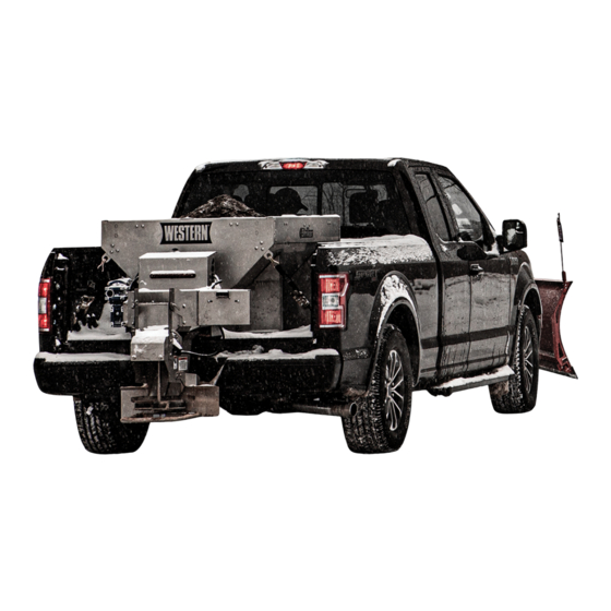
Striker™ Hopper Spreader
0.35 yd
& 0.7 yd
3
3
#98805, 98810
Owner's Manual
Original Instructions
CAUTION
Read this document before operating
or servicing the spreader.
This Owner's Manual is for Striker hopper spreaders
with serial numbers beginning with 200706 and higher.
This manual supersedes all editions with an earlier date.
Advertisement
Table of Contents

Related Manuals for Douglas Dynamics Western Striker 98805


Summary of Contents for Douglas Dynamics Western Striker 98805
- Page 1 Western Products, PO Box 245038, Milwaukee, WI 53224‑9538 • www.westernplows.com July 1, 2020 Lit. No. 74126, Rev. 00 Striker™ Hopper Spreader 0.35 yd & 0.7 yd #98805, 98810 Owner's Manual Original Instructions CAUTION Read this document before operating or servicing the spreader. This Owner's Manual is for Striker hopper spreaders with serial numbers beginning with 200706 and higher.
-
Page 3: Table Of Contents
TABLE OF CONTENTS PREFACE ..............4 OPERATING THE SPREADER—CAB CONTROL 17 Owner's Information Form ........4 Powering the Control .......... 17 SAFETY ..............5 Starting and Stopping Spreader ......17 Safety Definitions ..........5 Controlling Material Application ......18 Warning/Caution Labels ........5 BLAST/Maximum Application ...... -
Page 4: Preface
PREFACE This manual has been prepared to acquaint you with When service is necessary, bring your hopper the safety information, operation, and maintenance of spreader to your distributor. They know your spreader your new hopper spreader. Please read this manual best and are interested in your complete satisfaction. -
Page 5: Safety
SAFETY SAFETY DEFINITIONS WARNING/CAUTION LABELS Become familiar with and inform users about the WARNING warning and caution labels on the spreader. Indicates a potentially hazardous situation that, if not avoided, could result in death or NOTE: If labels are missing or cannot be read, see serious personal injury. - Page 6 0.7 yd³ hoppers only (0.35 yd³ hoppers have no cross bar). Lit. No. 74125/74126, Rev. 00 July 1, 2020...
-
Page 7: Serial Number Label
SAFETY SERIAL NUMBER LABEL SAFETY PRECAUTIONS Improper installation and operation could cause personal injury and/or equipment and property damage. Read and understand labels and the Owner's Manual before installing, operating, or making adjustments. WARNING • Driver to keep bystanders minimum of 25 feet away from operating spreader. -
Page 8: Fuses
SAFETY FUSES CAUTION If rear directional, CHMSL light, or brake The electrical system contains several blade-style stoplights are obstructed by the spreader, the automotive fuses. If a problem should occur and fuse lights shall be relocated, or auxiliary directional replacement is necessary, the replacement fuse must or brake stoplights shall be installed. -
Page 9: Ventilation
SAFETY VENTILATION TORQUE CHART WARNING CAUTION Vehicle exhaust contains lethal fumes. Read instructions before assembling. Breathing these fumes, even in low Fasteners should be finger tight until concentrations, can cause death. Never instructed to tighten according to the Torque operate a vehicle in an enclosed area without Chart. -
Page 10: Loading
LOADING This Owner's Manual covers vehicles that have been CAUTION recommended for carrying the hopper spreader. Please Never use wet materials or materials with see your local dealer for proper vehicle applications. foreign debris with any of these spreaders. These units are designed to handle dry, clean, CERTIFICATION free-flowing material. -
Page 11: Load Volume
LOADING LOAD VOLUME DETERMINING VEHICLE PAYLOAD Load Volume (yd WARNING Hopper Model Overloading could result in an accident or damage. Do not exceed GVWR or GAWR 0.35 yd³ 0.35 0.03 ratings as found on the driver‑side door 0.7 yd³ 0.85 0.06 cornerpost of the vehicle. -
Page 12: Determining Vehicle Payload Worksheet
LOADING Determining Vehicle Payload Worksheet Example: Material Type Dry Salt 8' Stainless Equipment installed when Steel Hopper vehicle was weighed Spreader Front Gross Axle Weight 6000 Rating [FGAWR] (lb) Rear Gross Axle Weight 7000 Rating [RGAWR] (lb) Gross Vehicle Weight 11,000 Rating [GVWR] (lb) Gross Vehicle Weight [GVW],... -
Page 13: Unpacking The Spreader
UNPACKING THE SPREADER REMOVE SHIPPING BRACKETS AND For 0.7 yd hopper spreaders: LOCATE COMPONENTS 1. Take off the top screen by removing the 3/8" flanged cap screws and the top screen brackets. Set the The spreader is shipped from the factory with its screen and all fasteners aside for reinstallation. -
Page 14: Mounting The Spreader
MOUNTING THE SPREADER CHUTE ASSEMBLY INSTALL HOPPER IN VEHICLE BED 1. To complete assembly of the chute, orient the NOTE: Periodically throughout the snow and ice spinner guard as shown. Fasten the spinner control season, verify that mounting devices are secure. deflector assembly to the chute enclosure using four 3/8”... -
Page 15: Install Tie-Down Straps
MOUNTING THE SPREADER 6. Move the spreader back into position. Install CAUTION the spreader to the vehicle bed using four Before drilling holes, check to be sure that no 5/8" Grade 5 bolts as required by the vehicle vehicle wiring or other components could be application, 5/8"... -
Page 16: Construct Sill Spacer
SPINNER DRIVE ASSEMBLY Install Tie‑Down Straps INSTALL SPINNER DRIVE ASSEMBLY Install tie-down straps from the tie-down loops on the NOTE: Complete the assembly installation in the spreader body to the truck frame. Use one strap per Install Chute Assembly section before proceeding with these instructions. -
Page 17: Operating The Spreader-Cab Control
OPERATING THE SPREADER – CAB CONTROL If any button is pressed on the control, it will wake and WARNING check again for spreader connection. If no spreader is Never operate equipment when under the detected, it will act as described above. If a spreader influence of alcohol, drugs, or medications that is detected, it will transition to Ready mode. -
Page 18: Controlling Material Application
OPERATING THE SPREADER – CAB CONTROL CONTROLLING MATERIAL Ready Mode APPLICATION Vehicle ignition is set to ACC or ON; cab control is OFF. Control has power. Spreader is detected. The material application settings can be adjusted while spreader is ON or OFF. Settings are shown by The Material Width and Material Flow control knobs the indicator lights around the control knobs. -
Page 19: Cab Control Codes - Table
OPERATING THE SPREADER – CAB CONTROL CAB CONTROL CODES Setup Codes Code Definition Procedure Calibrate the Empty Hopper setting. With control in ON mode, press and hold the left control knob until the Cb code displays. Calibration cycle is automatic.* Clear calibration data for Empty Hopper Press the right control knob to clear all calibration data during the setting;... - Page 20 OPERATING THE SPREADER – CAB CONTROL CAB CONTROL CODES continued Error Codes – Spreader Operation Stopped Code Definition Possible Cause Suggested Solution Excessive drive faults. Too many HO and/or SO Control times out for 60 seconds. error codes; hopper module Ensure that conveyor and/or spinner are not overheating.
-
Page 21: Setup Procedures
OPERATING THE SPREADER – CAB CONTROL SETUP PROCEDURES Adjust LED Brightness Level (LS and SL Codes) Calibrate the Empty Hopper Setting (Cb and EH Codes) The brightness setting of the cab control lights can be adjusted from 1 to 16. The factory default setting is 8. Calibrating the empty hopper setting enables the cab 1. -
Page 22: Operating The Spreader
OPERATING THE SPREADER SPREAD PATTERN ADJUSTMENT The spread pattern and amount of material dispensed depend on hopper chain drive speed, feed gate position, and shutter deflector setting. • Decreasing hopper drive speed and/or gate opening will decrease the amount of material coming to the spinner. -
Page 23: Material Spread Patterns
OPERATING THE SPREADER Material Spread Patterns Handle in Center Notch Handle in Handle in Center‑Left Notch Center‑Right Notch Handle in Left Handle in Right (driver‑side) Notch (curb‑side) Notch Lit. No. 74125/74126, Rev. 00 July 1, 2020... -
Page 24: Accessory Led Work Light
OPERATING THE SPREADER ACCESSORY LED WORK LIGHT 4. Insert the cotter pin into the locking pin. 5. Position the material receptacle or walk-behind The accessory work light can be purchased through spreader under the end of the conveyor. your authorized dealer. Follow the work light Installation Instructions to wire the accessory work 6. -
Page 25: Remove Spreader From Vehicle
OPERATING THE SPREADER REMOVE SPREADER FROM VEHICLE STORE THE SPREADER 1. Disconnect the vehicle-side harness from the The spreader can be stored on blocks or stands. Make hopper-side harness. sure the supports are stable and the ground beneath is firm enough that the spreader will not shift over time. 2. -
Page 26: Maintenance
MAINTENANCE AFTER FIRST USE 4. The hopper body should be slightly tilted toward the chute end to prevent any rainwater from pooling in the hopper. Tighten all mounting fasteners. 5. Use blocking to ensure that the spreader is stable. AFTER EACH USE At the End of Each Season CAUTION or After Extended Storage... -
Page 27: Grease Fittings
MAINTENANCE CAUTION Disconnect electric power at spreader electrical wiring harness connection and tag out if required before servicing or performing maintenance. GREASE FITTINGS To keep your spreader running smoothly, lubricate the grease fittings as shown after each use and at the end of each season. -
Page 28: Electrical Components
ELECTRICAL COMPONENTS VEHICLE HARNESS DIAGRAM Cab Control 18 ga Red 4-Way Connector To Vehicle Switched Accessory Vehicle Control Harness To Vehicle CHMSL Signal (tap located in cab) Connectors 18 ga Shielded Twisted-Pair Cable 6 ga Red 100A Fuse 4 ga Red 18 ga Black Vehicle 4 ga Black... -
Page 29: Electrical Control Box
ELECTRICAL COMPONENTS ELECTRICAL CONTROL BOX POSITIVE (+) Spreader Module Spinner Drive NEGATIVE Harness (–) Assembly Spinner Harness Chain Drive Assembly Harness Assembly ACC Tap To CHMSL White Black Lit. No. 74125/74126, Rev. 00 July 1, 2020... -
Page 30: Final Adjustments
FINAL ADJUSTMENTS I f Conveyor Chain Is Too Tight CONVEYOR PINTLE CHAIN TENSION 1. Loosen the jam nuts on both sides. Back off the To check the conveyor chain tension, see whether the idler take-up bolt evenly on both sides. Then chain is visible in the chain tension port. -
Page 31: Troubleshooting Guide
TROUBLESHOOTING GUIDE Please see your distributor for service. The Before servicing the spreader: troubleshooting reference table below may guide you • Review all safety information. in diagnosing the issue. • Confirm that all electrical connections are tight and clean. For a reference table of the cab control error codes, see the Operating the Spreader –... - Page 32 TROUBLESHOOTING GUIDE Problem Possible Cause Suggested Solution Unplug the spreader harness and tag out, if required, Spinner does not turn. before performing any of the following repairs. Motor is running. 1. Obstruction is preventing rotation. 1. Clear obstruction. Unplug the spreader harness and tag out, if required, before performing any of the following repairs.
- Page 33 This page intentionally left blank. Lit. No. 74125/74126, Rev. 00 July 1, 2020...
- Page 34 This page intentionally left blank. Lit. No. 74125/74126, Rev. 00 July 1, 2020...
- Page 35 This page intentionally left blank. Lit. No. 74125/74126, Rev. 00 July 1, 2020...
- Page 36 This product conforms to EU Machinery Directive 2006/42/EC, Directive 2011/65/EU (RoHS2), and UNECE R10.05. Copyright © 2020 Douglas Dynamics, LLC. All rights reserved. This material may not be reproduced or copied, in whole or in part, in any printed, mechanical, electronic, film, or other distribution and storage media, without the written consent of Western Products. Authorization to photocopy items for internal or personal use by Western Products outlets or spreader owner is granted.
Need help?
Do you have a question about the Western Striker 98805 and is the answer not in the manual?
Questions and answers