Advertisement
Quick Links
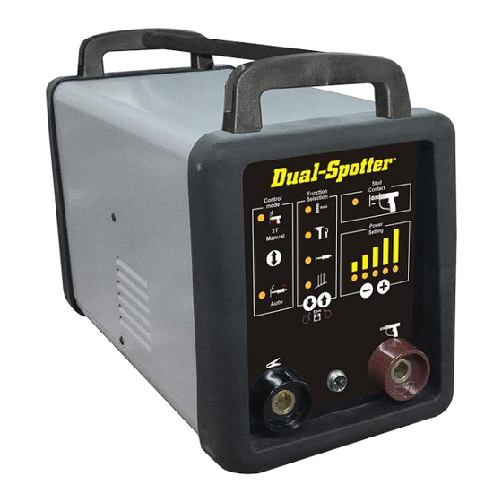
DUAL-SPOTTER
TM
ALUMINUM & STEEL
STUD WELDING SYSTEM
OPERATOR MANUAL
_____________________________________________________
IMPORTANT:
BEFORE STARTING THE EQUIPMENT, READ THE ENTIRE MANUAL.
THIS MANUAL MUST BE STORED IN A PLACE FAMILIAR TO ALL USERS FOR THE ENTIRE
OPERATIVE LIFE-SPAN OF THE MACHINE. THIS EQUIPMENT MUST BE USED SOLELY
FOR WELDING OPERATIONS BY SKILLED TECHNICIANS.
9800-03 01/10/20
Advertisement

Related Manuals for Nu-Tec Systems DUAL-SPOTTER

Summary of Contents for Nu-Tec Systems DUAL-SPOTTER
- Page 1 DUAL-SPOTTER ALUMINUM & STEEL STUD WELDING SYSTEM OPERATOR MANUAL _____________________________________________________ IMPORTANT: BEFORE STARTING THE EQUIPMENT, READ THE ENTIRE MANUAL. THIS MANUAL MUST BE STORED IN A PLACE FAMILIAR TO ALL USERS FOR THE ENTIRE OPERATIVE LIFE-SPAN OF THE MACHINE. THIS EQUIPMENT MUST BE USED SOLELY FOR WELDING OPERATIONS BY SKILLED TECHNICIANS.
- Page 2 SAFETY PRECAUTIONS - WELDING CAN BE HARMFUL TO YOURSELF AND OTHERS. 1) ELECTRIC SHOCK - May be fatal! Connect the welding machine to power lines according to applicable and NEMA regulations. Do not touch live electrical parts or electrodes with bare skin, gloves or wet clothing. Isolate yourself from exposed power, earth and the work piece bare metal.
- Page 3 1. DESCRIPTION OF TECHNICAL SPECIFICATIONS Rated Supply Voltage No-load Voltage Input Current (max.) Output Current (max.) Duty Duty-Cycle 2. Summary The machine utilizes microprocessor capacitor discharge for stud welding with capacity Ø2- Ø6mm. Stud materials may be mild steel, stainless steel, aluminum, titanium (Ti), brass and copper. Stud Welding time is about 3/1000s-6/1000s.
- Page 4 2-2. AL & Steel CD Spot Welding 2-2-1. AL Stud Welding 1. The stud pressed onto 2. Capacitor discharge 3. Completed AL material - Compression arc melts pin into puddle stud weld Capacitive discharge aluminum stud welding requires specially designed CD-Studs with arc-tip heads. CD stud welding requires very clean and contaminate free surface.
- Page 5 Set-Up Tab Shooter Tool 2. Discharge- 1. Washer contact 3. Finish welding power to work piece Capacitive discharge steel stud welding requires specially designed stud pins with arc-tip or pull tabs. CD stud welding on steel requires the correct pressure and power setting to “weld” to the surface of the panel but, due to the extremely short cycle time, there is no distortion, burn-through or oxidation on reverse side of panel.
- Page 6 Set-Up Slide Hammer...
-
Page 7: Operation
3. Cable Connections 1) For stud welding/spot welding-torch with earth cable Stud torch with earth cable STUD WELDING TORCH CABLE CONTROL CABLE WORK PIECE EARTH CABLE (ONE CABLE) 4. Operation: The machine is different from traditional spot welder as it uses patent capacitor discharge power source design. - Page 8 5. Control Panel A— There are two modes to select Auto mode: The torch and earth cable Fire-On-Contact with the panel. Designed only for slide hammer use! Manual mode: The torch trigger controls machine output. Note: If Auto or Manual LED is flickering, machine is B B1 recharging and cannot output power.
- Page 9 6. Stud Welding Torch Operation Earth tip shaft Earth Tip Collar Pressure adjustment End Tips Body Earth wire Handle Stud collet black plug to earth Output cable Trigger control cable plug Tab Holder from torch red plug to welding torch Stud collet or tab tip holder or slide hammer shaft installed into chuck and tighten.
- Page 10 Over time with insertion of many studs, the collet body jaws will expand and cause the stud to be loose in the collet. Use pliers to clamp collet jaws closed for good contact. This can greatly extend life of the stud collet body. 7.
- Page 11 9. Stud Welding Visual Test Please refer to the picture as follow, and assessment the stud welding results. 1.Voltage not enough 2.Correct voltage 3.Too high voltage The following situations may cause inferior welds: (1) The earth legs and the metal are not good connection. (Clean tips and base material) (2) Torch cable or earth cable is loose in machine connectors.
-
Page 12: Accessories List
ACCESSORIES LIST POS. CODE NO. DESCRIPTION PICTURE UNI-9516 Slide Hammer w/ T-Handle UNI-9520 Weld-Tip Extension w/ Earth Cable UNI-9521 Claw 4-Finger w/ M14 Mount DTK-8004 Slide Hammer Weld-tip M5 UNI-2101 Wiggle Wire 1 Lb. (0.5kg) UNI-2110 Spot Wire Tip UNI-1001 2.2 UNI-STUD Flexpert UNI-1002 2.6 UNI-STUD Flexpert HD... - Page 13 UNI-2040 Spot Pull Tab M4 Swivel Type UNI-9806 Stud collet M6 UNI-1262 Stud screw M6*16 (#6061) AL/SI UNI-1162 Stud screw M6*16 (#5052) AL/MG UNI-2060 Spot Pull Tab M6 Swivel Type UNI-1061 Pull Tab Straight UNI-1062 Pull Tab Twist UNI-9716 CD Chuck Wrench 14mm * 10mm UNI-9600 Tab Shooter Tool UNI-9817...
- Page 14 INSTRUCTION FOR CONSUMABLES USAGE CODE DESCRIPTION UNI-9705 Dent Stick Puller optional DTK-8004 Slide Hammer Weld-tip M5 UNI-9516 Slide Hammer w/ T-Handle Weld-Tip Extension w/ Earth UNI-9520 Cable UNI-9521 Claw 4-Finger w/ M14 Mount UNI-9524 Tip Holder Extended Tapered UNI-1001 2.2 UNI-STUD Flexpert UNI-1002 2.6 UNI-STUD Flexpert HD UNI-1004...
- Page 15 EXPLODED PARTS LIST MODEL 9802-03 Part No. Description Part No. Description 597N5830 PCB drive & capacitor EY11244C1X0101G5 bottom panel 597N5839 front panel 9802-03 VT091062-2 main transformer 707.0121 115VAC power cord EY11244C1Z0101+ inside panel 175N9037 control socket 530.0025 rubber foot 530.0024 511N0014 quick socket EY11244H0101B1...
Need help?
Do you have a question about the DUAL-SPOTTER and is the answer not in the manual?
Questions and answers