Advertisement
Table of Contents
- 1 Product Loading
- 2 Before Loading
- 3 Operation
- 4 Temperature Regulation
- 5 Switching on and off
- 6 Set Point Setting
- 7 Manual Defrosting
- 8 Alarm History
- 9 Alarm Reset
- 10 Rst Reset
- 11 Maintenance
- 12 Type Description
- 13 How to Order Spare Parts
- 14 Disposal of Packaging
- 15 Disposal of the Unit
- Download this manual
Advertisement
Table of Contents

Subscribe to Our Youtube Channel
Related Manuals for Zanotti zer0


Summary of Contents for Zanotti zer0
- Page 1 zer 0°- FZ MANUALE USO E MANUTENZIONE USE AND MAINTENANCE INSTRUCTIONS NOTICE DE MODE D’EMPLOI ET D’ENTRETIEN GEBRAUCHS – UND WARTUNGSHANDBUCH MANUAL DE USO Y MANUTENCIÓN...
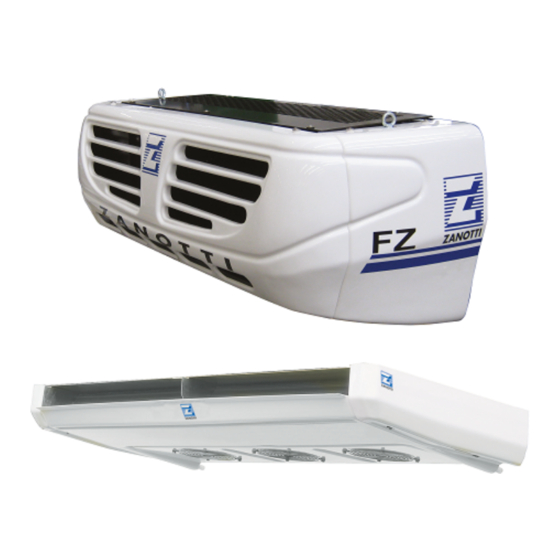
- Page 2 The ranges zer0° and FZ are the result of a simple and tested design and reliability. The purchase price and low cost of operation and management make this group ideal for installation on vehicles transporting with small / medium size.
- Page 3 INDEX 1. IMPORTANT NOTES AND SAFETY IDENTIFICATION Nameplate Summary table plates and stickers 3. PRODUCT LOADING 4. OPERATION Road mode operation Stand-by mode operation Temperature regulation Defrosting Heating function Multi-temperature operation 5. DESCRIPTION OF CONTROL Display Operations 5.2.1 Switching on and off 5.2.2 Set point setting 5.2.3...
- Page 4 1. IMPORTANT NOTES AND SAFETY When installing and using the unit please follow the recommendations listed here below. Installation shall be carried out in strict compliance with the diagrams and instructions supplied by the manufacturer. Damages due to improper connections are excluded. ...
- Page 5 For safe use of the unit, we suggest: ATTENTION Do not use water or steam when cleaning as the electrical components may be damaged. Keep condenser and evaporator clean. Stand-by operation in enclosed places: ensure good ventilation to the condenser. ...
- Page 6 IDENTIFICATION 2.1 Nameplate Each unit Zanotti Transblock is identified by a sticker. On the plate they are given the plant model, serial number and other information. For any problem, refer to the information on the data plate and note the plant model and serial number before calling your service personnel.
- Page 7 2.2 Summary table plates and stickers Refrigerant Condensate drain line Attention: hot or cold parts Attention: switch off before operating on the unit. Attention: danger of electrocution Connect this cable to a circuit breaker, never to the main line directly. Direction of rotation Colours of supply cable wires Attention –...
-
Page 8: Product Loading
Product loading Proper air circulation inside the insulated cell is essential to maintain the quality of the goods during transport. This ensures a uniform temperature distribution within the whole cell. If the air can not circulate freely around the load, you may create zones of heat or ice formations. -
Page 9: Operation
4. OPERATION 4.1 Road mode operation The control unit recognizes that the unit is in road mode when the ignition key of the vehicle is turned on. Battery unit Direct drive unit The unit is powered directly from the battery and An open-type compressor is driven by the engine the alternator of the vehicle on which it is of the vehicle, while the vehicle battery directly... - Page 10 Defrosting During cooling, the air releases moisture that accumulates gradually between the evaporator fins until freeze and block the passage of air which progressively reducing the efficiency of the system and subsequently causing damage. For this reason, regularly it does a defrost cycle in order to melt the ice accumulated and drain externally water. The control unit manages autonomously and periodically the beginning and the end of the defrosts.
- Page 11 Description of control 5.1 Display 5.1.1 Single temperature version 1. ON/OFF BUTTON: to switch on/off the unit (press 3 seconds). The red LED lights up when the unit is on. 2. SET button: to set the work set point of the unit. When the LED is on, setting is enabled. 3.
- Page 12 5.1.2 Multi-temperature version 1. ON/OFF BUTTON 1: to switch on/off the evaporator of compartment 1 (press 3 seconds). The red LED lights up when the unit is on. 2. SET BUTTON 1: to set the work set point of the evaporator of compartment 1. When the LED is on, setting is enabled.
-
Page 13: Switching On And Off
Operations The following instructions apply generally to both versions of the display. The only difference concerns the presence of dedicated keys for each compartment, respectively marked by numbers 1 and 2. 5.2.1 Switching on and off Road mode: Stand-by mode: The start of the motor vehicle by the ignition key Make sure that the supply voltage corresponds to that automatically enables the road mode, marked with the... -
Page 14: Set Point Setting
5.2.2 Set point setting: Push the botton the display shows the current value of the temperature in flashing red and the yellow icon push the buttons to se the desired value. push again or waiting 10” to save the new value. 5.2.3 Manual defrosting As mentioned the control unit operates autonomously defrosts. - Page 15 5.3.3 List of alarms and messages The following is the complete list of all the signals and alarms that may occur; also we outlined some of the possible causes and remedies can be implemented also by the user, remembering that if the problem persists you should contact an authorized service center.
-
Page 16: Rst Reset
Icon Alarm Description Possible causes Possible remedies Maintenance When is reached a set number of operation hours, are generated alarms SEE(SEE) stand-by maintenance or SEr(SEr) road mode maintenance, alternating with temperature display; This display can be temporarily reset by pressing any key and will recur after switching off and the following restart of the unit. -
Page 17: Maintenance
MAINTENANCE Proper maintenance is crucial for durability of the machine in operation and optimum performance and to ensure the security provided by the manufacturer. For reliable use in time of the group it is necessary to make a limited number of routine maintenance operations. For this follow the instructions of the booklet Maintenance 0MDL178 (provided with the documentation supplied with the unit) to which we give the maintenance schedule based on hours of operation: Service Road mode program (Abbreviation... -
Page 18: Type Description
SERVICE If necessary, you should contact your dealer in the first instance to identify the nearest service center. Alternatively you can contact your local Zanotti distributor; the list of national distributors is available on our website at the following link: http://www.zanotti.com/it/zanotti-nel-mondo... -
Page 19: How To Order Spare Parts
Zanotti designs its parts because they meet extreme demands of the refrigeration systems in vehicles. Invest in quality and reliability allows to supply spare parts that guarantee a longer life and increased maintenance intervals. The best way to ensure that your Zanotti unit remains efficient and reliable is to keep 100% Zanotti. Contact your dealer. - Page 20 Zanotti S.p.A. Via M.L. King, 30 - 46020 Pegognaga (MN) Italy Tel. 0376.5551 Fax 0376.536554 Info@zanotti.com www.zanotti.com...
Need help?
Do you have a question about the zer0 and is the answer not in the manual?
Questions and answers