Advertisement
Quick Links
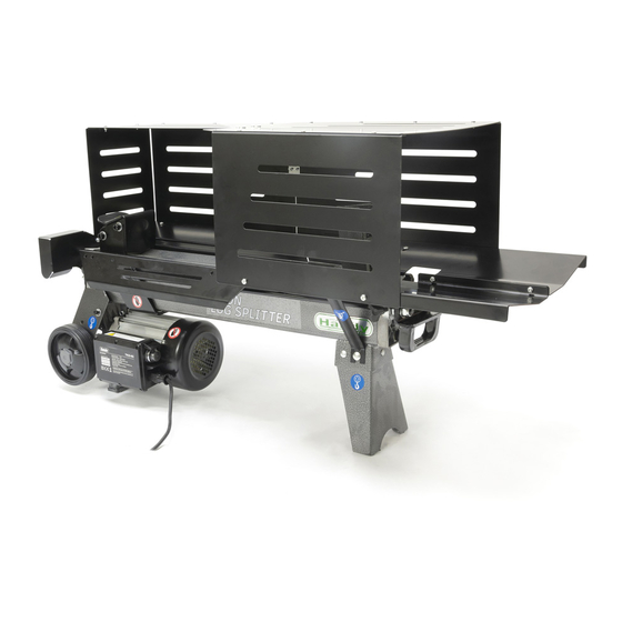
ADDED INFORMATION SHEET - THLS-6G & 4G LOG GUARD
Guard Bottom Plate
1. Mount the guard bottom plate to the rear guiding plate and secure with two M6×12 screws and locknuts
with a 5mm Allen Key and 10mm Spanner. Ensure the triangular longside sits against the cut away of the
rear guiding plate.
2. Loosen the socket head cap screw and big washer on the wheel bracket with a 5mm Allen Key, insert the
open end of support strut B between the big washer and wheel bracket and tighten screw with 5mm Allen
Key.
Socket Head Cap Screw
Rear Guiding Plate
Triangular Longside
Support Strut B
Open End of
Support Strut
Advertisement

Related Manuals for The Handy THLS-6G


Summary of Contents for The Handy THLS-6G
- Page 1 ADDED INFORMATION SHEET - THLS-6G & 4G LOG GUARD Guard Bottom Plate 1. Mount the guard bottom plate to the rear guiding plate and secure with two M6×12 screws and locknuts with a 5mm Allen Key and 10mm Spanner. Ensure the triangular longside sits against the cut away of the rear guiding plate.
- Page 2 3. Connect the upper end of support strut B to the guard bottom plate with cross head screw M6×12 and locknut M6 and then tighten with Phillips Screwdriver and 10mm Spanner. Support Strut B Log Tray A 1. Remove the Allen Key screw M6x12 with spring washer from the log splitter body, using 5mm Allen Key.
- Page 3 2. Align the mounting hole of the log tray A to the hole in the log splitter body and refit the M6x12 Allen Key screw with spring washer 6, using a 5mm Allen Key. Log Tray A 3. The right side of Log Tray A, is secured using Allen Key screw M16×12 and locknut M6 on to the rear guiding plate and secure with 5mm Allen Key and 10mm Spanner.
- Page 4 5. Connect the upper end of support strut A to log tray A with cross head screw M6×12 and locknut M6 and then tighten with Phillips Screwdriver and 10mm Spanner. Log Tray B Now rotate the machine 180 degrees. 1. Remove the Allen Key screw M6x12 with spring washer from the log splitter body, using 5mm Allen Key.
- Page 5 2. Align the two mounting holes of the log tray B to the holes on the side of the splitter. Insert one socket head cap screw M6×12 and spring washer 6 back into the mounting hole, using 5mm Allen Key. 3.
- Page 6 5. Connect the upper end of support strut A to the log tray B with cross head screw M6×12 and locknut M6 and then tighten with Phillips Screwdriver and 10mm Spanner. 6. Secure Log Tray A to Log Tray B, using the two cross head screw M6×12 and locknut M6 and then tighten with Phillips Screwdriver and 10mm Spanner.
- Page 7 Steel Guard 1. Attach the front guard plate to the logsplitter, using a M6x12 bolt and locknut. It is secured within the Control Lever Guard and tighten with Phillips Screwdriver and 10mm Spanner.
- Page 8 2. Align the holes of the guard side plates with the fitted trays and secure using M5x12 bolts and locking nuts using Phillips Screwdriver and 8mm Spanner.
- Page 9 3. Secure the two guard side plates together with the four hole, silver bracket and secure with cross head M5x12 screws and M5 locknuts and tighten with 5mm Allen Key and 8mm Spanner.
- Page 10 4. Attach the single guard side plate to fitted log trays on the working side of the logsplitter, using M5x12 screws and M5 locknuts and tighten with 5mm Allen Key and 8mm Spanner. 5. Now add the top guard plates, starting with the smaller plate, which sits above the working area. Secure it to the front guard plate and the rear of the two side guard plates, using using M5x12 screws and M5 locknuts and tighten with 5mm Allen Key and 8mm Spanner in the holes provided.
- Page 11 6. Now you can secure the large top plate to the two side guard plates, using M5x12 screws and M5 locknuts and tighten with 5mm Allen Key and 8mm Spanner in the holes provided. 7. The final step is to secure both top guards to one another, using the supplied silver plate and secure with M5x12 screws and M5 locknuts and tighten with 5mm Allen Key and 8mm Spanner in the holes provided.
Need help?
Do you have a question about the THLS-6G and is the answer not in the manual?
Questions and answers