
Subscribe to Our Youtube Channel
Summary of Contents for Precision Stairlifts LEGACY ELEGANCE II
- Page 1 Staying Home Corporation 2501 Anaconda Road Harrisonville, MO 64701 816-380-2427 www.stayinghome.com LEGACY ELEGANCE II Model SL19 Installation Manual January 10, 2019...
-
Page 2: Preliminary Checks
Preliminary Checks Installation Site Requirements _____ 115 VAC, 60 Hz, 3-wire grounded outlet within 6' of the top of the staircase. * Some states may require dedicated outlet. _____ Stair angle between 25° and 45°. _____ Indoor installation. Included with Shipment Tools Required _____ Aluminum track with gear rack and splice bars _____ Set of nut driver bits... -
Page 3: Typical Components
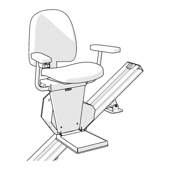
Typical Components Folding Armrests Unit Control Folding Seat under Armrest Limit Cam Manual Lowering Access Track Bracket Chassis Folding Footrest Extruded Aluminum Track Safety Pan Access Panel to Batteries, Etc. Circuit Breaker / Reset Install Switch LED Diagnostic Indicator Optional Key Switch... - Page 4 Underside of Chassis Travel Cable inside Energy Chain Upper Limit Switch Final Limit Switch Overspeed Governor Pinion Gear Drive Pinion Gear Lower Limit Switch...
- Page 5 Identify Track Pieces Upper Track Red paint on the end of the gear racks indicates Lower Track that end has been precision machined. Only butt-up the ends of gear racks that are red. If the end is not painted, it must be put toward the end of the track.
- Page 6 Installation Procedures for Stock Units Track Installation: Track and rack should be cut before installing them on the staircase Tracks are packaged in individual boxes. You will generally have 2-3 sections of track with steel gear rack, (4-6) track mounting brackets located in a small parts box located in seat box, and 1-2 sets of splice bars already pre-mounted on the track.
- Page 7 Right Hand Left Hand Installation Installation Gear rack is always on the right side as you look up from the bottom Apply a light coat of lithium grease on the gear rack and vertical sides of the track .
- Page 8 Splice Track Pieces Together Check the edges of the outside C-channels for rough edges. If there are any burrs, file them off before splicing the track Position the splice bars so they are half way inserted into one track. Tighten the set screws in the bars. Tap the large end of the 3/16"...
- Page 9 Secure the Track to the Stair Treads When the track is installed, there should be a 1" gap between the underside of the track and the stair nosings and 1/4" to 1/2" off the lower landing floor. The track should be at least 3" away from the wall 1"...
- Page 10 Insert the Chassis into the Track Chassis Rollers Remove the upper most section of gear rack to allow you to slide the chassis into the track easily. Ensure the chassis rollers and shim spacers are properly installed on the chassis axles. Two shims go onto each axle on the gear rack side and one shim on the opposite side.
- Page 11 With the chassis parked at the bottom limit, slide the energy chain/travel cable down along the inside of the track, beneath the gear rack, until there is a small loop under the chassis, beyond the point of where the travel cable is attached to the chassis. 2-Conductor Cable Chain Mounting Bracket Energy Chain is positioned...
- Page 12 Place the upper limit cam inside the track and se- cure by tightening the phillips head screw. End Cap Place the end plate onto the end of the track while Limit Cam routing the travel cable through the slot in the bot- tom of the end plate.
- Page 13 Place the footrest assembly onto the two socket Footrest head screws on the chassis. Use the keyhole pattern Assembly that offsets the footrest assembly toward the top end of the chassis. Connect the wire harnesses between the chassis and footrest assembly. Level the footrest and tighten the (4) socket head Wire screws (2 in front and 2 on back).
- Page 14 RF Remote Call-Send Controls The two key fobs (transmitters) and the seat control have been factory programmed. If you are installing two lifts in the same home, it is not necessary to change the program. Each trans- mitter and receiver is unique and has its own rolling code. If a key fob needs to be programmed, remove the safety pan from the bottom of the footrest to access the RF receiver.
- Page 15 AUDIO/VISUAL STATUS INDICATIONS The lift is equipped with a chassis mounted 3-color LED display light to indicate the operating condi- tion of the lift. Accompanying this is an audible alarm that will sound accordingly. STATUS LIGHT AUDIBLE ALARM CONDITION RED-YELLOW-GREEN 1 Second beep Power-up Cycle SOLID...
-
Page 16: Completion Procedures
Completion Procedures SERVICE LINE 877.378.4275 (Mon-Fri 8:00 – 5:00 CST) Completion Checklist The following features must be verified as operational before the stair lift can be released for use: _______ Upper and lower limits: Verify the lift stops automatically at the top and bottom of the track. _______ Charger: Verify that the light on the charger changes from green to amber when the lift is running.
Need help?
Do you have a question about the LEGACY ELEGANCE II and is the answer not in the manual?
Questions and answers