Advertisement
Quick Links
Advertisement

Related Manuals for Axiom CNC Series


Summary of Contents for Axiom CNC Series
- Page 1 Axiom CNC Safety Enclosure Assembly Manual BG Precision Date: 28 July 2019...
- Page 2 Manufacturer: AXIOM PRECISION AXIOM TOOL GROUP TAIWAN Agent and Appointed Reseller BG Precision PTY LTD Unit 1/82 Brunel Road SEAFORD 3198 VIC Australia Mob: +61 (0)405685515 Email: info@bgprecision.com.au Website: www.bgprecision.com.au WARNING Read & understand operators manual before using this machine.
- Page 3 Please ensure you read the operational manuals for this AXIOM CNC router machine prior to attempting to use the system.
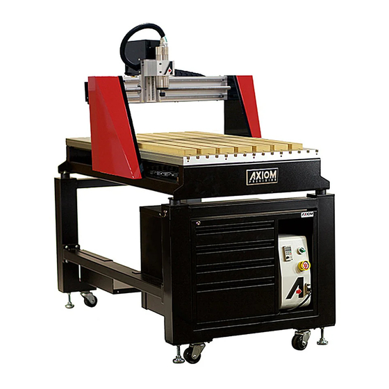
- Page 4 Figure 1 Axiom AR8 with full Safety Enclosure and additional touch screen display ANDLING YOUR XIOM MACHINE The CNC router table assembly is heavy. Please use a secure means and use caution when lifting onto the stand. At least 3-4 able bodies persons are needed to lift the machine onto the stand.
- Page 5 LUMINIUM ROFILE SSEMBLY HINTS...
- Page 6 Figure 3 Corner Alignment When connecting two aluminium extrusion components together you must ensure a square and flush fit. We achieve this by placing a straight edge across the joint while tightening the pre-tensioning anchor grub screw. This is very important to all the enclosure components aligning correctly.
-
Page 7: Step 1 - Setting Up The Stand
TAND ONTENTS Figure 4 Axiom Stand Packaging Figure 5 Axiom Stand contents Packaging contents for the Axiom Precision Stand (ARS400/600/800): 2-Stand upright (front & back) 2-Cross braces 1-Lower shelf plate 1-Stand hardware package... - Page 8 Remove all contents from shipping boxes. Do not discard carton or packing material until assembly is complete. Accessories commonly ship inside machine or stand packaging and can be easily over looked. TAND SSEMBLY Tools required for assembly: #2 Philips-Screwdriver 10mm, 13mm and 17mm sockets and socket wrench 24mm open-end wrench 2mm and 3mm Allen key Spirit Level...
- Page 9 b. The small rubber pads should now be between the flange and the top surface of the brace. This will help prevent unwanted movement and scratching. XIOM OOLBOX 1- Turn the tool-box upside down. Install (1) of each hanger on either side of the toolbox using the installed rivnuts and (2) 3mm cap-screw each.
- Page 10 NCLOSURE BASE ASSEMBLY The final step of the setting up the stand assembly is fixing the machine enclosure base to the stand. To assist with locating the assemblies correctly we have provided 4 x M4x10mm screws that should be used to help align the enclosure base assembly to the stand assembly (See Figure 12).
- Page 11 At least 3-4 able bodies persons are needed to lift the machine onto the stand. To avoid damage, be careful to never lift the router by the gantry. Always lift the Axiom CNC machine under the BLACK STEEL FRAME. You should sight under your Axiom CNC Table;...
- Page 12 If using a forklift, keep forks under the black steel frame to avoid damaging the wiring and mechanics of the machine. Place a scrap piece of lumber beneath the router assembly and carefully slide forks beneath the steel base. Figure 16: Ensure forks extent the entire way across the machine IMPORTANT NOTE Make sure the forks extend through to the other side of the machine for safe lifting.
- Page 13 1- Position router over the stand and align holes on router mounting flanges and the enclosure base assembly holes being careful to make sure the stand is properly oriented with the machine front. Stand front is the side you placed the toolbox in as per Figure 17. Figure 17 Installing the Router Table on the Stand 2- Place rubber bushing over the holes in the stand.
- Page 14 4- Now is a good time to place your control box into its correct location in the toolbox and feed all the connection cables through the hole at the back Figure 20 Axiom Controller in toolbox Figure 21 Connection Cables 5- Connect the two barrel connections to the back of the Router Table as per Figure 22.
-
Page 15: Step 3 - Enclosure Assembly
3 - E NCLOSURE ASSEMBLY 1- The first step of the enclosure assembly is the front left corner upright. Ensure it is flush with cross-member and tighten accordingly. Please note orientation of hinge brackets. Figure 23 Front Left Upright 2- The second step is the right-hand side assembly. Ensuring the front hinges as facing in towards the centre of the machine slide the right-hand side assembly along the enclosure base cross members as per the picture shown. - Page 16 3- Now proceed to the back of the machine. The rear assembly should be positioned as shown making sure the hinges are positioned in towards the machine for the side doors. Take care of the barrel connections at the back of the machine. There are two black brackets to hold the polycarbonate in place that can be secured to the side installed previously.
- Page 17 4- Now we can fit the single front bottom cross member as per the pictures shown. Take note that the magnetic door stops should be facing up. Again, it is very important to ensure all connections are flush on both sides Figure 29 Bottom front cross member Figure 30 Bottom front cross member complete 5- Now we can proceed to hang the doors.
- Page 18 Figure 32 Doors Fitted 6- Place the top assembly as shown in the picture below. This step may require a few hands and a safe working platform to reach the top of the enclosure. Figure 33 Preparation for top assembly...
- Page 19 With the doors shut the step will be easier to allow the top assembly to rest in place. Figure 34 Top assembly Location 7- Remove the bubble wrap and position the control electronics in place as per the pictures below. You can pop out the slot covers to place the electronic cable in neatly inside.
- Page 20 8- Now you can secure each corner of the top assembly the four uprights. You must ensure a flush connection for perfect enclosure alignment. Figure 37 Top Assembly Complete...
- Page 21 Figure 38 Door Interlock Keys Figure 39 Safety controller connection to Axiom Control box The final step in this section is to connect the safety controller to the Axiom control box. This connection is identified in Figure 39. Step 3 is now complete.
- Page 22 2. All E-stops keyed or none keyed must be reset (Pulled out) 3. Axiom Controller powered on 4. STEP 1 SET UP THE NETWORK complete as per Axiom Machine user manual 5. STEP 2 INSTALL THE UCCNC SOFTWARE as per Axiom Machine user manual 6.
- Page 23 “T ” ESET OGIC IS CTIVE If the following message comes up “The Reset Logic Is Active” (Figure 42) the best way to diagnose is the Diagnostic Tab as per Figure 43. If the E-stop function is highlighted green, it means one of the conditions of section 5.1 SAFETY ENCLOSURE OPERATION CONDITIONS are not met.
- Page 24 5 – D NTERLOCK ALIGNMENT While we do are best to align all doors and interlocks at initial assembly, they may need adjustment from the final assembly on site or simply need adjustment overtime. There are several adjustment points which will be highlighted in this section. Please note that if the interlocks are not alignment correctly the machine cannot be activated which is the safest situation.
- Page 25 Figure 45 Door Interlock Key Alignment As a final note the Door Bracket in Figure 46 is vital to the operation of the enclosure and should not be removed or adjusted. It ensures you close the doors in the correct order and that both doors are locked via the mechanical lock in the interlock.
-
Page 26: Enclosure Dimensions
1 – E PPENDIX NCLOSURE IMENSIONS... -
Page 28: Enclosure Components
2 - E PPENDIX NCLOSURE OMPONENTS...
Need help?
Do you have a question about the CNC Series and is the answer not in the manual?
Questions and answers