Table of Contents
Advertisement
Quick Links
Advertisement
Table of Contents

Related Manuals for Advantech ProView Series


Summary of Contents for Advantech ProView Series
- Page 1 User Manual EKI-5729PI & EKI-5624PI ProView Series Ethernet Switches...
- Page 2 No part of this manual may be reproduced, copied, translated or transmitted in any form or by any means without the prior written permission of Advantech Co., Ltd. Information provided in this manual is intended to be accurate and reliable. How- ever, Advantech Co., Ltd.
- Page 3 This product has passed the CE test for environmental specifications when shielded cables are used for external wiring. We recommend the use of shielded cables. This kind of cable is available from Advantech. Please contact your local supplier for ordering information.
- Page 4 Caution! Cautions are included to help you avoid damaging hardware or losing data. e.g. There is a danger of a new battery exploding if it is incorrectly installed. Do not attempt to recharge, force open, or heat the battery. Replace the battery only with the same or equivalent type recommended by the man- ufacturer.
- Page 5 The sound pressure level at the operator's position according to IEC 704-1:1982 is no more than 70 dB (A). DISCLAIMER: This set of instructions is given according to IEC 704-1. Advantech disclaims all responsibility for the accuracy of any statements contained herein.
- Page 6 Der arbeitsplatzbezogene Schalldruckpegel nach DIN 45 635 Teil 1000 beträgt 70dB(A) oder weiger. Haftungsausschluss: Die Bedienungsanleitungen wurden entsprechend der IEC- 704-1 erstellt. Advantech lehnt jegliche Verantwortung für die Richtigkeit der in die- sem Zusammenhang getätigten Aussagen ab. EKI-5729PI & EKI-5624PI User Manual...
- Page 7 Safety Precaution - Static Electricity Follow these simple precautions to protect yourself from harm and the products from damage. To avoid electrical shock, always disconnect the power from your PC chassis before you work on it. Don't touch any components on the CPU card or other cards while the PC is on.
-
Page 8: Table Of Contents
Contents Chapter Product Overview ....... 1 Specifications.................... 2 Hardware Views..................3 1.2.1 Front View..................3 Figure 1.1 Front View ..............3 Figure 1.2 Front View ..............4 Figure 1.3 System LED Panel ............. 5 1.2.2 Rear View ..................6 Figure 1.4 Rear View..............6 1.2.3 Top View.................. - Page 9 Figure 3.4 InstallShield Wizard 3 of 4 ........25 Figure 3.5 InstallShield Wizard 4 of 4 ........25 Utility Menu Map ..................26 Figure 3.6 Configuration Utility Overview ........26 Menu Bar....................27 3.5.1 View Menu .................. 27 Figure 3.7 View > Settings > Main Form Setting ....... 27 Figure 3.8 View >...
-
Page 10: Product Overview
Chapter Product Overview... -
Page 11: Specifications
1.1 Specifications Specifications Description Interface I/O Port EKI-5624PI: 4 x 10/100BaseT(X) with PoE + 2 x 10/100/1000BaseT(X) EKI-5729PI: 8 x 10/100/1000BaseT(X) with PoE + 2 x 10/100/1000BaseT(X) Power Connector 6-pin screw Terminal Block (including relay) Physical Enclosure Metal Shell Protection Class IP30 Installation... -
Page 12: Hardware Views
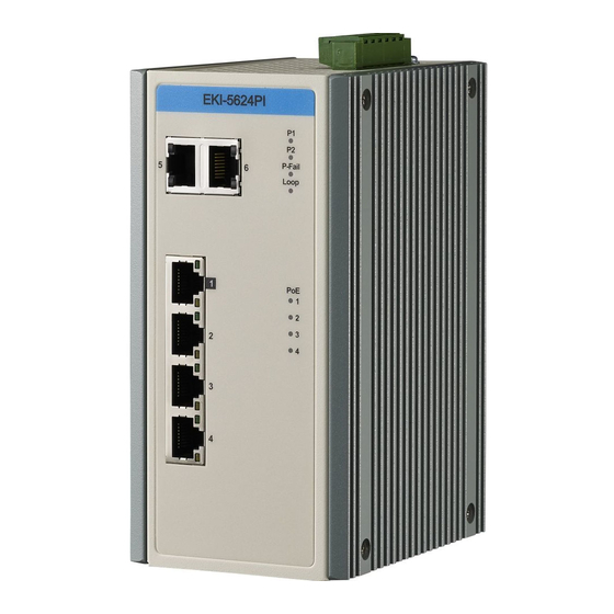
1.2 Hardware Views 1.2.1 Front View The following view applies to EKI-5624PI. EKI-5624PI P-Fail Loop Figure 1.1 Front View No. Item Description ETH port Two 10/100/1000BaseT(X) ports. ETH port Four 10/100BaseT(X) with PoE ports. LNK/ACT LED Link activity LED. Speed LED Fast Ethernet: ... - Page 13 The following view applies to EKI-5729PI. EKI-5729PI P-Fail Loop Figure 1.2 Front View No. Item Description ETH port Two 10/100/1000BaseT(X) ports. ETH port Eight 10/100/1000BaseT(X) with PoE ports. LNK/ACT LED Link activity LED. Speed LED Gigabit Ethernet: Green: 1000M ...
- Page 14 System LED Panel P-Fail Loop Figure 1.3 System LED Panel No. LED Name LED Color Description PW1 LED Solid green Powered up. Powered down or not installed. PW2 LED Solid green Powered up. Powered down or not installed. P-Fail Solid red When PW1 or PW2 is disconnected, the LED lights.
-
Page 15: Rear View
1.2.2 Rear View The following view applies to EKI-5624PI and EKI-5729PI. Figure 1.4 Rear View No. Item Description DIN-Rail mounting Mounting plate used for the installation to a standard DIN rail. plate EKI-5729PI & EKI-5624PI User Manual... -
Page 16: Top View
1.2.3 Top View The following view applies to EKI-5624PI and EKI-5729PI. V2+V2- V1+V1- DC12-24V 1A@24V PWR2 P-Fail PWR1 Figure 1.5 Top View Item Description Terminal block Connect cabling for power and alarm wiring. 1.2.4 Bottom View The following view applies to EKI-5624PI and EKI-5729PI. Figure 1.6 Bottom View ... -
Page 17: Switch Installation
Chapter Switch Installation... -
Page 18: Installation Guidelines
2.1 Installation Guidelines The following guidelines are provided to optimize the device performance. Review the guidelines before installing the device. Make sure cabling is away from sources of electrical noise. Radios, power lines, and fluorescent lighting fixtures can interference with the device performance. ... -
Page 19: Verifying Switch Operation
2.2 Verifying Switch Operation Before installing the device in a rack or on a wall, power on the switch to verify that the switch passes the power-on self-test (POST). To connect the cabling to the power source see “Power Supply Installation” on page 16. At startup (POST), the System LED blinks green, while the remaining LEDs are a solid green. -
Page 20: Installing The Switch
2.3 Installing the Switch 2.3.1 DIN Rail Mounting The DIN rail mount option is the quickest installation option. Additionally, it optimizes the use of rail space. The metal DIN rail kit is secured to the rear of the switch. The device can be mounted onto a standard 35mm (1.37”) x 75 mm (3”) height DIN rail. -
Page 21: Wall-Mounting
Once the bottom is clear of the DIN rail, lift the device straight up to unhook it from the DIN rail. DIN Rail Figure 2.2 Removing the DIN-Rail 2.3.2 Wall-Mounting The wall mounting option provides better shock and vibration resistance than the DIN rail vertical mount. - Page 22 Secure the wall mount plates with M3 screws, see the following figure. Figure 2.3 Installing Wall Mount Plates Once the wall mounting plates are secure on the device, you will need to attach the wall screws (x6). Locate the installation site and place the switch against the wall, making sure it is the final installation location.
- Page 23 Align the wall mount plate over the screws on the wall. Install the wall mount plate on the screws and slide it forward to lock in place, see the following figure. Figure 2.5 Wall Mount Installation Once the device is installed on the wall, tighten the screws to secure the device. EKI-5729PI &...
-
Page 24: Connecting The Switch To Ethernet Ports
2.4 Connecting the Switch to Ethernet Ports 2.4.1 RJ45 Ethernet Cable Wiring For RJ45 connectors, data-quality, twisted pair cabling (rated CAT5 or better) is rec- ommended. The connector bodies on the RJ45 Ethernet ports are metallic and con- nected to the GND terminal. For best performance, use shielded cabling. Shielded cabling may be used to provide further protection. -
Page 25: Power Supply Installation
2.5 Power Supply Installation 2.5.1 Overview Warning! Power down and disconnect the power cord before servicing or wiring the switch. Caution! Do not disconnect modules or cabling unless the power is first switched off. The device only supports the voltage outlined in the type plate. Do not use any other power components except those specifically designated for the switch device. -
Page 26: Grounding The Device
Make sure to separate input and output wiring. Label all wiring and cabling to the various devices for more effective manage- ment and servicing. Note! Routing communications and power wiring through the same conduit may cause signal interference. To avoid interference and signal degra- dation, route power and communications wires through separate con- duits. -
Page 27: Wiring A Relay Contact
By connecting the ground terminal by drain wire to earth ground the switch and chas- sis can be ground. Note! Before applying power to the grounded switch, it is advisable to use a volt meter to ensure there is no voltage difference between the power supply’s negative output terminal and the grounding point on the switch. - Page 28 Make sure the power is not connected to the switch or the power converter before proceeding. Loosen the screws securing terminal block to the terminal block receptor. Remove the terminal block from the switch. Figure 2.11 Removing a Terminal Block Insert a small flat-bladed screwdriver in the V1+/V1- wire-clamp screws, and loosen the screws.
- Page 29 If there is no gap between the terminal block and the terminal receptor, the ter- minal block is seated correctly. Figure 2.13 Securing a Terminal Block to a Receptor EKI-5729PI & EKI-5624PI User Manual...
-
Page 30: Configuration Utility
Chapter Configuration Utility... -
Page 31: Overview
3.1 Overview This section describes the installation procedures for the Advantech EKI Device Con- figuration Utility. The Configuration Utility is the software tool for setting up and monitoring the EKI- 5729PI & EKI-5624PI. 3.2 Enabling ProView Function The configuration of a ProView switch can be accessed by using EKI Device Config- uration Utility. -
Page 32: Installing The Configuration Utility
Microsoft .NET Framework version 2.0 or greater is required for this application. Insert the Advantech EKI Device Configuration Utility CD-ROM into the CD- ROM drive (whereas E:\ is the drive name of your CD-ROM) on the host PC. Use Windows explorer or the Windows Run command to execute the setup pro- gram, the path for the setup program on the CD-ROM is as follows: E:\EKI_Device_Configuration_Utility_v2.01.exe... - Page 33 Once the InstallShield Wizard screen displays, click Next to proceed with the installation. Figure 3.2 InstallShield Wizard 1 of 4 The Software License Agreement displays, press I Agree to continue or Cancel to stop the installation. Figure 3.3 InstallShield Wizard 2 of 4 EKI-5729PI &...
- Page 34 The InstallShield continues and a status screen displays. The default installation path is C:\Program Files\EKI Device Configuration Utility. Figure 3.4 InstallShield Wizard 3 of 4 Once the installation of the package is finished a Configuration Utility Setup screen displays. Click Finish to conclude the process and exit the InstallShield Wizard.
-
Page 35: Utility Menu Map
The EKI Configuration Utility can be installed on different operating systems, how- ever, Windows 7 is the recommended version. Click Start > All Programs > EKI Device Configuration Utility > Advantech EKI Device Configuration Utility. The EKI Device Configuration Utility screen appears, see the following figure. -
Page 36: Menu Bar
3.5 Menu Bar 3.5.1 View Menu 3.5.1.1 Utility Settings Click View > Settings to configure utility settings. Figure 3.7 View > Settings > Main Form Setting Item Description Main Window Settings Maximum Main Window Check the box to enable the limiting of main windows on-load to On Load the maximum value. - Page 37 Figure 3.8 View > Settings > Device Manager Item Description Device Manager Tree View Grouping Click the drop-down menu to enable or disable grouping. Show Empty Device Type Check the checkbox to show empty device type node or not. Node Expand New Appended Check the checkbox to expand a new appended device node or Device Node...
-
Page 38: Management Menu
3.5.2 Management Menu Item Description Configuration Wizard Start the software wizard (setup assistant) to leads you through the VCOM configuration process for device server product. Clear Device List and Clear all device list and re-search devices. Search Again Search Again Re-search devices. -
Page 39: Treeview
3.7 TreeView The TreeView configuration area displays the selected device’s configurable settings. From this area you can directly group devices in the favorite’s list. See “Utility Menu Map” on page 26. 3.8 Information Panel The Information Panel area displays the selected device’s related information. See “Utility Menu Map”... -
Page 40: Chapter 4 Managing Switch
Chapter Managing Switch... -
Page 41: Discovering Switches
4.1 Discovering Switches 4.1.1 First Time Installation Enabling ProView Function See “Enabling ProView Function” on page 22 for further information. Configuring Network Settings EKI Device Configuration Utility provides two ways to configure network settings: DHCP + Auto IP Settings or Static Settings. DHCP + Auto IP Settings Select Ethernet under the desired device. - Page 42 Click Apply to confirm the settings. Figure 4.2 Configuring a Static IP Setting EKI-5729PI & EKI-5624PI User Manual...
-
Page 43: Discovering Switches
4.1.2 Discovering Switches Auto Search Only devices within the same network domain can be listed through the search func- tion. Once a device is listed, the features and configuration details are accessible by clicking on the device name. Figure 4.3 Auto Searching Screen To search for a device: EKI-5729PI &... -
Page 44: Group Management
From the Tool Bar, click the Search Again button. Figure 4.4 Selecting Search Again Note! Access to the utility’s full function list requires administrator privileges. Clearing Device List and Search Again The search list can be cleared for a new search request by clicking the Clearing Device List and Search Again button. - Page 45 Enter a group name and click OK. Figure 4.5 Adding a Group The group is created and is available in the Favorite’s List. Favorite's List A favorite’s list is simple a way to organize the available devices by a category. There are three ways to create a favorite’s list: selecting a device, selecting an IP address, and selecting an IP address range.
- Page 46 Select Add to Favorite. Figure 4.6 Adding a Switch to Favorites In the event that there are existing groups, you can select the specific favorite group to include the selected device. Adding an IP Address From the Tool Bar, click the Add IP Address to Favorite button.
- Page 47 Click OK to add the IP address into the favorites list Figure 4.7 Add Favorite In the event that there are existing groups, you can select the specific favorite group to include the selected IP address. Adding an IP Address Range From the Tool Bar, click the Search for a Range of IP Addresses button.
-
Page 48: Configuring The System
Click OK to add the range into the favorites list. Figure 4.8 Add Favorite In the event that there are existing groups, you can select the specific favorite group to include the selected IP address range. 4.1.4 Configuring the System Changing Device Name Select the device to configure by clicking on it. - Page 49 Click Apply to configure the device. Figure 4.9 Changing Device Name The device name is changed. Setting Modbus/TCP Idle Time Select the device to configure by clicking on it. In the Configuration Area, select the System tab. Locate the Modbus/TCP Host Idle Time(s) field. Enter a variable representing the idle time for the Modbus/TCP host function.
- Page 50 Click Apply to configure the function. Figure 4.10 Setting Modbus/TCP Idle Time The Modbus/TCP idle time is now set. Setting LLDP Select the device to configure by clicking on it. In the Configuration Area, select the System tab. Under LLDP, check Enable LLDP Feature to enable the LLDP feature. This feature is used by the device to advertise its identity, capabilities, and neighbors throughout the network.
- Page 51 In the SNMP Trap Setting selection, enter the IP address of the SNMP trap server. Figure 4.11 Setting SNMP Setting PoE Select the device to configure by clicking on it. In the Configuration Area, select the PoE tab. Select the radio-box next to the target port then click on it to check and enable the PoE function on that port.
- Page 52 – Temperature (Celsius) Figure 4.12 Setting Modbus/TCP Idle Time EKI-5729PI & EKI-5624PI User Manual...
-
Page 53: Modbus/Tcp Mapping
4.2 Modbus/TCP Mapping The data map addresses of Advantech switches shown in the following table start from Modbus address 30001 for function code 4. In the given example, the address offset 0x1000 (hex) equals Modbus address 34097, while the address offset 0x1100 (hex) equals Modbus address 34353. - Page 54 Catelog Name Data Type Interpr Address Address Description etation Offset (Hex) System Firmware 2 words 32 bits 0x020A 30523 Firmware Version Info Version Word 0 Hi byte = major Word 0 Lo byte = minor Word 1 Hi byte = release Word 1 Lo byte = build Ethernet...
- Page 55 Catelog Name Data Type Interpr Address Address Description etation Offset (Hex) Port Info Port 4 Sta- 1 word 16 bits 0x1003 34100 Port 5 Sta- 1 word 16 bits 0x1004 34101 Port 6 Sta- 1 word 16 bits 0x1005 34102 Port 7 Sta- 1 word 16 bits 0x1006...
- Page 56 Catelog Name Data Type Interpr Address Address Description etation Offset (Hex) Port Info Port ASCII 0x1400 35121 ~ Port Description Descrip- words chars 35741 Port Description = tion 0x166C "100RX,RJ45." Word 0 Hi byte = '1' Word 0 Lo byte = '0' Word 1Hi byte = '0' Word 1 Lo byte = ‘R’...
- Page 57 Catelog Name Data Type Interpr Address Address Description etation Offset (Hex) Port Info Link Up 1 word 16 bits 0x1700 35889 ~ Link Up Counter Counter 35920 Ex: port link up counter 0x171F = 13 Received MODBUS response: 0x000D Port 1 Link 1 word 16 bits 0x1700 35889...
- Page 58 Catelog Name Data Type Interpr Address Address Description etation Offset (Hex) Port Info Port 5 PoE 1 word 16 bits 0x1804 36149 Voltage Port 6 PoE 1 word 16 bits 0x1805 36150 Voltage Port 7 PoE 1 word 16 bits 0x1806 36151 Voltage...
- Page 59 Catelog Name Data Type Interpr Address Address Description etation Offset (Hex) Port 5 PoE 1 word 16 bits 0x1844 36213 Power Port 6 PoE 1 word 16 bits 0x1845 36214 Power Port 7 PoE 1 word 16 bits 0x1846 36215 Power Port 8 PoE 1 word 16 bits...
- Page 60 Catelog Name Data Type Interpr Address Address Description etation Offset (Hex) Packet Tx Packets 4 words 64 bits 0x2000 38193 ~ Tx Packets Info Counter 38317 Ex: port 1 Tx Packet 0x207C Amount = 11223344 Received MODBUS response: 0xAB4130 Word 0 = 0x0000 Word 1 = 0x0000 Word 2 = 0x00AB Word 3 = 0x4130...
- Page 61 Catelog Name Data Type Interpr Address Address Description etation Offset (Hex) Port 6 Rx 4 words 64 bits 0x2114 38469 Packets Port 7 Rx 4 words 64 bits 0x2118 38473 Packets Port 8 Rx 4 words 64 bits 0x211C 38477 Packets Packet Port 9 Rx...
- Page 62 Catelog Name Data Type Interpr Address Address Description etation Offset (Hex) Rx Error 2 words 32 bits 0x2300 38961 ~ Rx Error Packets Packets 39023 Ex: port 1 Rx Packet Counter 0x233E Amount = 11223344 Received MODBUS response: 0xAB4130 Word 0 = 0x00AB Word 1 = 0x4130 Port 1 Rx 2 words 32 bits...
- Page 63 EKI-5729PI & EKI-5624PI User Manual...
- Page 64 No part of this publication may be reproduced in any form or by any means, electronic, photocopying, recording or otherwise, without prior written permis- sion of the publisher. All brand and product names are trademarks or registered trademarks of their respective companies. © Advantech Co., Ltd. 2007...
Need help?
Do you have a question about the ProView Series and is the answer not in the manual?
Questions and answers