Otto Bock B400 Instructions For Use Manual
Hide thumbs
Also See for B400:
- Service manual (82 pages) ,
- Instructions for use manual (68 pages) ,
- Using manual (152 pages)
Table of Contents
Advertisement
Quick Links
Advertisement
Table of Contents

Related Manuals for Otto Bock B400


Summary of Contents for Otto Bock B400
- Page 1 B400 Instructions for Use...
-
Page 3: Table Of Contents
Control Unit ............31 2.6 Safety Requirements for Care, Maintenance 6.3.1 Control Panel ............31 and Disposal ............16 6.3.2 Switching On and Off ........... 32 2.7 Requirements for the User ........17 6.3.3 Driving Function ........... 33 2.8 Safety Functions........... 17 6.3.4 Battery Capacity LED Indicator ......34 2.9 Warning Symbols and Type Plates ....... 18 6.3.5 Range ..............35 Product Description ..........21 Ottobock B400 |... - Page 4 Error ..............44 Maintenance, Cleaning and Care ....... 48 9.1 Maintenance Intervals .......... 48 9.2 Changing the Fuse ..........51 9.3 Changing Tyres ............ 51 9.4 Cleaning and Care ..........53 9.4.1 Disinfection ............53 Technical Data ............ 54 Disposal .............. 58 4 | Ottobock B400...
- Page 5 List of Figures Fig. 19 Disassembling drive wheel ......52 List of Figures Fig. 20 Disassembling front wheel ....... 52 Fig. 1 Signage on the B400 ........18 Fig. 2 Main components ..........22 Fig. 3 Anti-tipper B400 ..........22 Fig. 4 Fuse holder ............. 23 Fig. 5 Folding size ............. 24 Fig. 6 Release strap for the backrest ......25 Fig. 7 Removing the side panel ......... 26 Fig. 8 Adjusting the side panels ......... 26 Fig. 9...
-
Page 6: General Information
B400 resulting from improper use; in such cases, the user has power wheelchair from Otto Bock Mobility Solutions GmbH. sole liability. The instructions contain all the information that is needed to The B400 may only be used by persons trained to use it. use the power wheelchair safely, to determine the possible Training users and attendants to use the power wheelchair causes of a malfunction and to help eliminate it. 6 | Ottobock B400... -
Page 7: Field Of Application
General Information are required for protecting persons from danger and for en- Fitting considerations: suring that the B400 is operated safely and correctly. „ Body size and body weight The operational safety of the B400 can only be ensured if it (max. load capacity 140 kg / 309 lbs) is used properly in accordance with the information con- „ Physical and psychological limitations tained in these instructions for use. The user is ultimately „ Age of the patient responsible for accident-free operation. „ Home conditions „ Evironment Field of Application The modular design of the power wheelchair makes it suit-... -
Page 8: Safety
The B400 power wheelchair has been constructed in ac- INFORMATION cordance with the currently valid technical rules and is safe Information regarding operation. Information for service to operate. The safety of the B400 power wheelchair has personnel. been confirmed by CE certification and the declaration of conformity. 8 | Ottobock... -
Page 9: General Safety Instructions
Only use original manufacturer’s options. The optional documents must be observed and complied with. The in- components may be mounted only as described here. structions for use must be available to the user at all times. Failure to comply will void the warranty. CAUTION Risk of accident and injury due to improper use. The B400 may only be used properly. The B400 may only be used by persons trained to use it. CAUTION Risk of burns when near to fire. The back upholstery and seat cushion of the power wheelchair are not highly flam- mable, but can however catch fire. Therefore utmost cau- tion near any sources of open flame or sparks, especially lit cigarettes, is required. -
Page 10: Safety Requirements For Transportation, Storage And Assembly
(such as lap belt) which are offered by Ottobock Please note; batteries that are not leak proof or that might and suitable restraint systems are used. not be transported in an upright position must be removed Only one person may be transported in the B400 at any and wrapped to ensure they are leak proof and short-cir- one time. For optimum protection of the occupants in case cuit-proof. of an accident, use the seats and corresponding restraint For more information please visit the www.iata.org web- systems installed in a wheelchair accessible vehicle while site. Ottobock recommends directly contacting the airline... - Page 11 Risk of tipping as a result of incorrectly mounted anti- fuse for shipping or when the power wheelchair is not be- tipper. To ensure safe driving operation, the anti-tipper ing used for an extended period of time. must have been mounted correctly and must be in proper condition. INFORMATION The tyres of the power wheelchair contain chemical sub- INFORMATION stances that can react to other chemical substances Prior to using the power wheelchair, all the necessary me- (such as cleaning agents, acids). chanical adaptations (e. g. mounting special controls) and Black tyres contain soot particles that can cause discol- software settings (e. g. programming the control) must be oration and black marks. For this reason, place a suitable made to comply with the individual requirements and abili- mat underneath the wheelchair, if it is not going to be used ties of the user. The settings may only be made by trained over an extended period of time. specialists who have been authorised by Ottobock. Ottobock B400 |...
-
Page 12: Safety Requirements For Operation
The power wheelchair may only be operated if all safety functions, e.g. the automatic brakes, are functional. Brake WARNING failure can result in serious accidents with fatal injuries. Risk of injury if the power wheelchair tips over during driving. The B400 has been approved for driving on inclines WARNING and slopes of no more than 7° (12 %). Navigating inclines Risk of accidents and injury due to incorrect configura- above this percentage value is not permitted. tion settings. Modified parameter settings in the configu- The critical obstacle height of the B400 is 50 mm. It is not ration can lead to changes in driving characteristics. - Page 13 If any faults, defects or other dangers that can lead to WARNING Risk of tipping due to centre of gravity shifting. Getting personal injury are detected, the power wheelchair must to know how the power wheelchair reacts when the centre be put out of operation immediately. of gravity shifts, for example, on slopes or inclines or when clearing obstacles like steps and curbs should be done Ottobock B400 |...
- Page 14 Risk of accident as a result of bad tyres. Check visually Damage due to exposure to extreme temperatures. before every use that the tread depth is sufficient and that The B400 may be used within a temperature range of the tyres are inflated to the correct tyre pressure. -25 °C to +50 °C. It must not be operated outside this temperature range.
- Page 15 Safety NOTICE INFORMATION Damage caused by overload. The maximum load for the If the driving mode is changed while driving, the power B400 is 140 kg / 309 lbs. This load must not be exceeded. wheelchair will accelerate or decelerate. NOTICE INFORMATION Electric interference due to electromagnetic fields. The The controls of the power wheelchair are protected ac- power wheelchair has been tested according to EMC cording to protective system IP 54 and can thus be used regulations. Take care of the following particularities dur-...
-
Page 16: Safety Requirements For Care, Maintenance And Disposal
Incorrect settings nent damage to the battery. can lead to brake failure. NOTICE WARNING Damage of electronics as a result of penetrating water. Risk of injury due to explosive gases. Explosive gases Never use a water jet or high-pressure cleaning apparatus can develop while the batteries are charging. For this rea- for cleaning the power wheelchair. Avoid direct contact of son, the following safety precautions are to be taken when water with electronics, motors, and batteries under all cir- charging the battery: cumstances. 16 | Ottobock B400... -
Page 17: Requirements For The User
The power wheelchair must be inspected for functional judgment. reliability and driving safety at least once a year by an au- thorised specialist. Safety Functions INFORMATION Defective batteries must be disposed of properly in ac- INFORMATION cordance with country-specific regulations. In dangerous situations, the B400 can be turned off at any time using the on/off button. When the button is pressed, the power wheelchair brakes immediately and the electric Requirements for the User functions will be stopped. If any malfunctions occur such as an insufficient supply of CAUTION energy to the brake, the software will recognize them and Risk of accident and injury as a result of improper use. -
Page 18: Warning Symbols And Type Plates
Safety Warning Symbols and Type Plates Fig. 1 Signage on the B400 18 | Ottobock B400... - Page 19 Safety Label/Type Plate Explanation A Type designation B European article number (EAN) C Maximum load capacity (see Section „Technical Data“) D Maximum climbing ability (see Section „Technical Data“) E Maximum speed (see Section „Technical Data“) F Symbol for separate collection of electric and electronic devices. Components of the power wheelchair and the batteries must not be disposed of like regular domestic waste. G CE marking – product safety in conformity with EC Directives H Serial number Read the Instructions for Use prior to using the product. J Manufacturer / address K Product reference number Ottobock B400 |...
- Page 20 Safety Label/Type Plate Explanation A Electric driving operation: lock motor brake B Manual pushing mode: unlock motor brake Risk of pinching. Do not reach into the danger area. Table 1 Signage on the B400 20 | Ottobock B400...
-
Page 21: Product Description
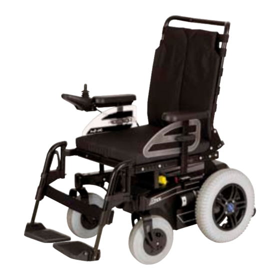
| Delivery and Preparation for Use Product Description Product Description Delivery and Preparation for Use The B400 power wheelchair is suitable for indoor and out- Delivery door use. It is compactly designed and easy to manoeuvre for use indoors. The powerful drive system supplied by two INFORMATION 12 V batteries and the drive wheels allow obstacles to be The options included in the delivery depend on the product overcome easily (application class B of EN 12184) and pro- configuration that has been selected for the power wheel- vide safe driving characteristics. chair. The VR2 control unit is used to control the power wheel- Delivery includes: chair. The control unit comprises a control panel for entering „ Adapted power wheelchair with main components the driving commands and for displaying the current state of (see fig. 2) the functions as well as a controller that uses the input data „ Battery Charger to control the drive motors. Data transmission is realised via... -
Page 22: Initial Operation
Delivery and Preparation for Use Fig. 3 Anti-tipper B400 Initial Operation WARNING Danger of suffocation. The packing material must be kept away from children. Prior to putting the power wheelchair into operation, the Fig. 2 Main components completeness (see fig. 2) and function of all its components 1 Backrest 5 Brake release must be checked. Before the power wheelchair can be... -
Page 23: Transportation And Storage
The power wheelchair may only be used for transportation in a wheelchair accessible vehicle if the safety compo- nents (such as lap belt) which are offered by Ottobock and suitable restraint systems are used. Only one person may be transported in the B400 at any one time. For optimum protection of the occupants in case of an accident, use the seats and corresponding restraint systems installed in a wheelchair accessible vehicle while it is in operation. For more information on the use of the B400 as a seat in a wheelchair accessible vehicle, please refer to our bro- chure “Using your Wheelchair / Mobility Base with Seat-... -
Page 24: Fig. 5 Folding Size
For this reason, place a suitable mat underneath the wheelchair, if it is not going to be used over an extended period of time. Black tyres can leave black traces on the ground INFORMATION under some circumstances. For this reason, we recommend choosing grey tyres when using the power wheelchair main- ly indoors. Direct sunlight/UV light causes the tyres to age INFORMATION prematurely. As a result, the tread surface hardens and cor- ner pieces break out of the tread. Whenever possible, avoid parking the wheelchair Fig. 5 Folding size INFORMATION outdoors. Regardless of wear and tear, the tyres should be Tyres contain chemical substances that can react to other replaced every 2 years. chemical substances (such as cleaning agents, acids, etc.). Remove the fuse for shipping or when the power INFORMATION wheelchair is not being used for an extended period of time. 24 | Ottobock B400... -
Page 25: Operation
(e.g. Eu- roLock A24.20). After the power wheelchair has been set and adjusted, the attachment screws and/or nuts must be firmly retight- ened. During tightening observe torques when specified. Various adjustments can be made to the power wheelchair. The seat height, seat width and seat angle have been set in accordance with the indications on the customer order form and may only be changed by the specialist dealer. The following items can be adapted by the user: Fig. 6 Release strap for the backrest „ Back angle „ Armrest height „ Armrest position „ Lower leg length If need be, the footrests and side panels can be removed. Ottobock B400 |... -
Page 26: Side Panel With Armrest
Adapting the armrest to the forearm length: Slide the armrest forwards or backwards and engage in the slot cor- responding to the desired position (see fig. 8, right). Tighten the screws again after making the adjustment. Fig. 7 Removing the side panel After remounting the side panel, do not forget to firmly retighten the thumb screw. Fig. 8 Adjusting the side panels 26 | Ottobock B400... -
Page 27: Control Panel
Later changing of the control panel's mounting position from the left to the right side or vice versa may only be carried out by specialist dealers. Fig. 9 Adapting the control panel Adapting the Control Panel to Arm Length Firmly re-tighten the screws after making adjustments. To adapt the control panel to the arm length of the user, you If the control panel rail is too long, the protruding INFORMATION must loosen the three screws on the underside of the arm- part can simply be cut off with a saw. rest using a 3 mm Allen wrench (see fig. 9). You can now slide the control panel backwards and forwards. Ottobock B400 |... -
Page 28: Footrest
Adjusting the Lower Leg Length (see fig. 11) 3. Pull the footrest up to remove it. 1. Loosen the Allen head screws on the footplate bar using a size 5 Allen key. Reassembly 1. Reinsert the footrest from above by placing it in the hold- 2. Move the footplate up or down to adapt the height to the ing device and swinging it forward until the footrest lock individual lower leg length and seat cushion thickness. engages. 3. Retighten the screws. 2. Reattach the calf band to the holding device. The footrest bar must not be pulled out of the INFORMATION holding device by more than 160 mm. 28 | Ottobock B400... -
Page 29: Getting Into And Out Of The Power Wheelchair
CAUTION where the user will get into the wheelchair. Bring the power Risk of injury if the power wheelchair starts rolling. wheelchair as close as possible to the place where its user When getting into or out of the power wheelchair, the is sitting. wheelchair controls must always be switched off. This will automatically engage the motor brake. If the control panel is on the side the user wants to use to get into/out of the wheelchair, then undo the hook and loop closures that fix the cable for the control panel. Then care- fully lay down the side panel with the control panel on the Ottobock B400 |... -
Page 30: From The Front
6.1.2. If necessary, remove the footrest, see section 6.1.4. The user can then slide onto the wheelchair’s seat from the side. Use of a transfer board will make this even easier. 6.2.2 From the Front Flipping up the two footplates makes it possible for the user to get into and out of the wheelchair from the front (fig. 12). The space for getting into/out of the wheelchair can be in- creased by swinging the footrests to the side (fig. 13). Fig. 12 Footplates flipped up The assistance of an attendant or a transfer lifter make it easy for the user to get into or out of the power wheelchair. Use of a rotation plate is also possible. Fig. 13 Footrests swung to the side 30 | Ottobock B400... -
Page 31: Control Unit
The charging/programming receptacle is on the underside. The control panel is used to switch the power wheelchair on and off, to enter driving commands and to display the current state of certain functions and compo- nents. Ottobock B400 |... -
Page 32: Switching On And Off
The LEDs show the battery capacity (see section 6.3.4) worse. The control panel of the power wheelchair is turned on or off Speed Level LED indicator The LEDs show the currently selected speed level. by pressing the On/Off key (see fig. 14, item 6). If the con- trol panel is not used for an extended period of time, the wheelchair turns off automatically. It is also possible to switch off the power wheelchair with the on/off key during driving. In this case, the wheelchair brakes immediately until it stops. 32 | Ottobock B400... -
Page 33: Driving Function
„ Do not cross obstacles with differences in height of automatically activates the brake function, which brings the more than 50 mm. wheelchair to a halt. When standing still, the mechanical „ Do not cross steps or curbs without braking first. brakes are automatically active so the power wheelchair The power wheelchair has been approved for driving on in- cannot move. clines and slopes of no more than 7° (12 %). You are not Ottobock B400 |... -
Page 34: Battery Capacity Led Indicator
In particular, changes to the speed, acceleration, braking tery capacity displayed on the control panel can differ or joystick settings can lead to unexpected and therefore more significantly from the actual battery capacity. uncontrollable operating performance with a risk of acci- dents. INFORMATION Always test the driving characteristics of the power wheel- Immediately after switching the power wheelchair on, the chair after configuration / programming is complete. battery indicator shows the battery capacity saved before Programming must only be completed by authorised per- the wheelchair was switched off the last time. The exact sonnel. Neither Ottobock nor the control unit manufacturer battery status is displayed after driving a short distance. are liable for damages caused by programming that was not properly / professionally adapted to the abilities of the The battery indicator on the LED display consists of 10 seg- wheelchair user. ments and shows the remaining battery capacity. 34 | Ottobock B400... -
Page 35: Range
„ Battery capacity „ Age of the batteries Recharge battery, if possible „ Ambient temperature Low battery, recharge urgently „ Driving conditions (e.g. terrain profile, condition of sur- face, use of lights) Battery is charging „ Charging method Running light „ Use of power options Battery: undervoltage „ Body weight of user Flashing light Battery: overvoltage Flashing light Table 2 Battery indicator on the control panel Ottobock B400 |... -
Page 36: Drive Lock
Operation 6.3.6 Drive Lock Indication Information The control unit of the B400 power wheelchair features an Running light LEDs Drive-away Lock electronic drive-away lock. This function is activated/deacti- Speed Level LED indicator vated via control panel. Table 3 Drive-away lock indicator on the control panel Activating the drive-away lock: Deactivating the drive-away lock: 1. With the control unit switched on, press and hold the 1. After switching on, the battery capacity indicator is off On/Off switch. -
Page 37: Releasing And Locking The Brake
„ When moving on inclined paths, the person pushing cally deactivate the driving function. The unlocked brake will the power wheelchair must provide the appropriate be indicated by the flashing “Battery Capacity” LED. brake force. „ The brake function may only be released in the pres- Once the brake unlocking lever has been re- INFORMATION ence of an attendant. leased, all braking systems are deactivated. „ Should the user be unable to release the brake himself, the brake can be released by the attendant. Ottobock B400 |... -
Page 38: Batteries
Break release indicator on the control panel Batteries INFORMATION Before doing any maintenance work on the batteries, please read the battery manufacturer‘s warnings thor- oughly! The B400 power wheelchair is equipped with two 50 Ah/ 12 V AGM batteries (maintenance free). The batteries are located under the seat of the power wheel- chair. See section 6.3.4 for battery capacity display on the control panel. -
Page 39: Battery Charging
We also recom- Ottobock B400 |... -
Page 40: Battery Charger
„ Always place the rubber feet of the battery charger on a level surface. 6.5.2 Battery Charger „ Protect the battery charger from direct sunlight to prevent the charger from getting any warmer than it already is. WARNING Explosion hazard as a result of sparks. Always switch „ The location where the battery charger is installed must off the battery charger and remove the mains plug before be dry and well ventilated. Avoid letting dust and dirt disconnecting the battery. enter the battery charger. „ To clean the charger, use a dry cloth. 40 | Ottobock B400... -
Page 41: Accessories
Risk of accidents due to tipping during operation. Driv- mains supply, then from power wheelchair. ing over obstacles such as steps or curbs is only allowed at reduced speed (max. 3 km/h). Always approach obsta- 5. Turn on the controls. The wheelchair is ready for driving. cles at a right angle and cross over them without stop- Please see the instructions for use supplied with the battery ping. charger for further details on use and on the LED indicators. The curb climbing assist is used to clear curbs and steps that have a maximum height of 10 cm. To cross an obstacle: „ Slowly approach the obstacle. „ Remove the footrests if required. Ottobock B400 |... -
Page 42: Lap Belt
CAUTION Risk of injury due to incorrect positioning of lap belt. „ Make sure the buckle is centred in front of the body to avoid pressure points/pinch points. „ Ensure that the lap belt is not too tight against the body. Fig. 16 Curb climbing assist „ Remove any objects or clothing which get caught. The lap belt provides additional stabilisation and keeps the user from sliding out of the seat. 42 | Ottobock B400... -
Page 43: Fig. 17 Adjusting The Lap Belt
Accessories Applying the lap belt 1. Push the two halves of the buckle together so they en- gage. The belt buckle must snap in place with an audi- ble click. 2. Pull on the belt to ensure that it is locked. Releasing the lap belt 1. Press the red release button. The buckle opens. Adjusting the belt length The belt length can be adjusted on both sides. Fig. 17 Adjusting the lap belt 1. Position both buckle halves in the middle of the body. 1 Belt buckle 2. The positions of the tongue and buckle can be varied when they are positioned at a right angle in relation to the belt. The excess belt length is held by the plastic sliders. Ottobock B400 |... -
Page 44: Failures/Troubleshooting
All problems that have ever occurred are saved in a list and soon as possible! can be retrieved, for example, in case of a general overhaul of the power wheelchair. The saved data can be used to determine future service and maintenance intervals, for ex- ample. 44 | Ottobock B400... - Page 45 Failures/Troubleshooting CAUTION Risk of accident due to uncontrolled driving behaviour. Uncontrolled movements can occur during the operation of the power wheelchair as a result of malfunction. In this case, please contact your authorised dealer immediately. NOTICE Malfunction on the control unit. When the joystick is ac- tivated while the brakes are unlocked, the control system emits an error signal on the control panel. If this is not the case, there is a malfunction that must be corrected imme- diately by a specialist dealer. An error affects one or several functions of the power wheel- chair. The system is not fully operational until the error has been corrected. Ottobock B400 |...
- Page 46 Poor cable connection to e.g. defective plug Check connection to the left the left motor motor Defective motor Check motor Short circuit on the battery e.g. broken cable Check battery connection to connection to the left motor the left motor Poor cable connection to e.g. defective plug Check connection to the right the right motor motor Defective motor Check motor Short circuit on the battery e.g. broken cable Check battery connection to connection to the right the right motor motor Driving function is blocked or battery charger is connected Disconnect battery charger due to external influences Joystick error Joystick not in zero position when Switch joystick to zero position switching on prior to switching on 46 | Ottobock B400...
- Page 47 Failures/Troubleshooting Flashing LED Error / Warning Cause Possible Corrective Action Controller error Controller defective Check all connections Brake release Brake release open Check the motor brakes/ Check the connections to controller Battery overvoltage Voltage too high Continue driving slowly Battery contacts loose Check plug contacts Communication error Poor cable, loose plug connection Check connections between control panel (joystick) and Controller Table 5 Status and error messages Ottobock B400 |...
-
Page 48: Maintenance, Cleaning And Care
Ottobock may be used. Failure to comply will render the warranty null and void. INFORMATION Should you encounter problems during maintenance, con- tact your authorised dealer. The power wheelchair is to be checked and serviced once a year by an authorised dealer. Maintenance Intervals The correct function of the power wheelchair should be checked every time before using it. The items listed in ta- ble 6 must be checked by the user at the indicated intervals. 48 | Ottobock B400... - Page 49 Maintenance, Cleaning and Care Components Activity Daily Weekly Monthly Armrest and side Fastening screws tightened panel Armrest and control panel secured Prior to every use Check armrest for damage Drive wheels Wheels must rotate freely and without axial run out Central nut on the driving shaft tightened Check if wheel mounts are seated securely Directional stability of the entire wheelchair Tyres Air pressure (printed on the sidewall of the tyre) Sufficient tread depth, at least 1 mm Check for damage Electronics Control system free of errors Prior to every use If battery charger does not show any error messages on the LEDs Check plug connections Brake Activate brake lever while control system is switched on Brake function active with engaged brake Ottobock B400 |...
- Page 50 Maintenance, Cleaning and Care Components Activity Daily Weekly Monthly Footrest Check ratchet mechanism for functionality and secure seating; check footplates for damage Swivelling Fork seated in the receiver without play wheels/casters Wheels must rotate freely and without axial run out Fastening nut tightened Padding Proper condition of padding Seat attachment Check if attachment screws are seated securely Table 6 Maintenance measures and intervals 50 | Ottobock B400...
-
Page 51: Changing The Fuse
To change the tyre of a drive wheel, proceed as follows: „ Secure the wheelchair to prevent it from tilting to the side Fig. 18 Fuse holder by placing a suitable base under the drive unit support. 1 Cap, open „ To dismount a drive wheel, loosen the four Allen head 2 Fuse, inserted screws in the middle of the wheel (fig. 19) with 8 mm Al- 3 Fuse holder len wrench and remove the wheel. Ottobock B400 |... -
Page 52: Fig. 20 Disassembling Front Wheel
Maintenance, Cleaning and Care „ If the inner tube of a drive wheel needs to be replaced, To change the tyre of a front wheel, proceed as follows. loosen all Allen head screws on the inner side of the rim „ To dismount the front wheel, loosen the screw of the axle with 8 mm Allen wrench and pull apart the two-piece rim. using a 6 mm Allen wrench (see fig. 20, item 1) and pull The defective inner tube is now freely accessible and can be out the axle. replaced. „ Loosen all Allen head screws (see fig. 20, item 2) with 8 mm Allen wrench and separate the two-piece rim. The defective inner tube is now freely accessible and can be replaced. Fig. 20 Disassembling front wheel Fig. 19 Disassembling drive wheel 1 Axle screw 2 Allen head screw 52 | Ottobock B400... -
Page 53: Cleaning And Care
Damage to power wheelchair components. Do not use 9.4.1 Disinfection any aggressive cleansing agents, solvents, or hard brush- Disinfect all parts of the wheelchair. es for cleaning the power wheelchair. Never use a water jet or high-pressure cleaning apparatus for cleaning the Important information about disinfection power wheelchair. „ Water based disinfectants should be used. Observe the usage information provided by the manufacturer. INFORMATION „ Prior to disinfection, clean the seat and back upholstery, Prior to disinfection, clean the seat and back upholstery seat cushion, control panel, and armrest. as well as the seat cushion, the control panel and the arm- rest. Ottobock B400 |... -
Page 54: Technical Data
Technical Data General information Application class (according to DIN EN Class B 12184) Dimensions and weights Seat width 380 – 420 mm Seat depth 380 – 460 mm Seat height 450 mm Armrest height 240 – 360 mm Armrest length 260 mm Lower leg length 350 – 440 mm Back height 450 or 550 mm Back angle 0/10/20/30° Overall width 580 mm Totoal height 1030 mm Total legth 1080 mm Turning radius 870 mm Turning circle* 1450 mm 54 | Ottobock B400... - Page 55 Technical Data Dimensions and weights Tyre size: Front wheel 9" Drive wheel 14" Air pressure front: printed on the sidewall back: 2.5 bar Weight empty 95 kg/210 lb Shipping weight* See weight empty*, of which: (* The specified weight varies according to Side panel: < 1 kg (2.2 lbs) the selected options and model.) Footrest (standard): approx. 1 kg (2.2 lbs) Max. load capacity 140 kg / 309 lbs (patient weight) Electrical Installation** IP protection class (according to DIN 60529) IPX4 Operating voltage 24 V Batteries: AGM batteries 2 � 12 V, 50 Ah (5C) Ottobock B400 |...
- Page 56 Technical Data Electrical Installation** Motors: Motor power 2 x 200 watt IP protection class (according to DIN EN 60529) IP44 Control: model VR2 IP protection class (according to DIN EN 60529) IP44 Operating voltage 24 V DC Max. output current per motor 60 A Backup 80 A For more information, see the instructions for use supplied for the battery Battery charger charger Driving Data Speed 7,2 km/h Maximum safe inclination (climbing ability)*** 7° (12 %) Obstacle height that can be cleared: 50 mm Distance range (on level surface)**** approx. 35 km 56 | Ottobock B400...
- Page 57 Technical Data Driving Data Braking distance at 7 km/h: 1200 mm (horizontal); (according to DIN EN 12184:2009)***** 2400 mm (incline) Operating temperature -25 °C to +50 °C Transport and storage temperature range -40 °C to +65 °C Protection against corrosion Corrosion protection Dip-coated frame * 3 -point turn by 180° ** T he product meets all requirements specified in ISO 7176-14. *** I n individual cases, the continuous climbing ability can be significantly lower than the value specified. **** T he specified range was determined under defined conditions in accordance with ISO 7176-4 specifications. In practice the range can be reduced by up to 50 %. For information on this, see the section «Range» in the instructions for use (user). ***** T he braking distance can be correspondingly longer due to user weight, installed options and condition of the tyres as well as weather and surface conditions. Table 7 Technical data Ottobock B400 |...
-
Page 58: Disposal
CAUTION Based on market observations and the current state of tech- nology, the manufacturer has calculated that the B400 There is a risk of polluting the environment with bat- tery acid. The batteries of the power wheelchair contain power wheelchair can be used for a period of 5 years, pro- a toxic acid. They must not be disposed of with regular vided that it is used properly and that the service and main- domestic waste and the battery acid must not enter the tenance instructions are observed. Periods during which the... -
Page 59: Legal Information
This product meets the requirements of the 93/42/EWG guidelines for medical products. This product has been classified as a class I product according to the classifica- tion criteria outlined in appendix IX of the guidelines. The declaration of conformity was therefore created by Ottob- ock with sole responsibility according to appendix VII of the guidelines. Ottobock B400 |... -
Page 60: Warranty Terms And Conditions
13.3 Warranty Terms and Conditions Further information on the warranty terms and conditions can be provided by the authorised personnel supplying the power wheelchair or by Ottobock Service (see inside back cover for addresses). 13.4 Trademarks All denotations within this accompanying document are sub- ject to the provisions of the respective applicable trademark laws and the rights of the respective owners, with no restric- tions. All brands, trade names or company names may be regis- tered trademarks and are subject to the rights of the respec- tive owners. Should trademarks in this accompanying document fail to be explicitly identified as such, this does not justify the con- clusion that the denotation in question is free of third-party rights. 60 | Ottobock B400... - Page 61 Kundenservice/Customer Service Europe Africa Asia/Pacific Otto Bock HealthCare Deutschland GmbH Otto Bock Italia Srl Us Otto Bock Algérie E.U.R.L. Otto Bock Australia Pty. Ltd. 37115 Duderstadt · Germany 40054 Budrio (BO) · Italy Mackle-Ben Aknoun · Alger · DZ Algérie Baulkham Hills NSW 2153 · Australia T +49 (0) 5527 848-3433 · F +49 (0) 5527 848-1460 T +39 (0) 051 692-4711 · F +39 (0) 051 692-4720 T +213 (0) 21 913863 · F +213 (0) 21 913863 T +61 (0) 2 8818 2800 · F +61 (0) 2 8814 4500 healthcare@ottobock.de info.italia@ottobock.com information@ottobock.fr healthcare@ottobock.com.au Otto Bock Healthcare Products GmbH Otto Bock Benelux B.V. Otto Bock Egypt S.A.E. Beijing Otto Bock 1070 Wien · Austria 5692 AK Son en Breugel · The Netherlands Mohandessein - Giza · Egypt Orthopaedic Industries Co., Ltd. T +43 (0) 1 5269548 · F +43 (0) 1 5267985 T +31 (0) 499 474585 · F +31 (0) 499 476250 T +202 (0) 330 24 390 · F +202 (0) 330 24 380 Beijing, 100015, P.R. China vertrieb.austria@ottobock.com info.benelux@ottobock.com info@ottobock.com.eg T +8610 (0) 8598 6880 · F +8610 (0) 8598 0040 news-service@ottobock.com.cn Otto Bock Adria Sarajevo D.O.O. Industria Ortopédica Otto Bock Unip. Lda. Otto Bock South Africa (Pty) Ltd 71000 Sarajevo · Bosnia-Herzegovina 1050-161 Lisboa · Portugal...
- Page 62 Ihr Fachhändler/Your specialist dealer: Versandanschrift für Rücksendungen/Address for Returns: Otto Bock Manufacturing Königsee GmbH Lindenstraße 13 · 07426 Königsee-Rottenbach/Germany Otto Bock Mobility Solutions GmbH Lindenstraße 13 · 07426 Königsee-Rottenbach/Germany T +49 (0) 69 9999 9393 · F +49 (0) 69 9999 9392 ccc@ottobock.com · www.ottobock.com Ottobock has a certified Quality Management System in accordance with ISO 13485.
Need help?
Do you have a question about the B400 and is the answer not in the manual?
Questions and answers