
Related Manuals for HAFRO NEW BI-SIZE Junior Series

Summary of Contents for HAFRO NEW BI-SIZE Junior Series
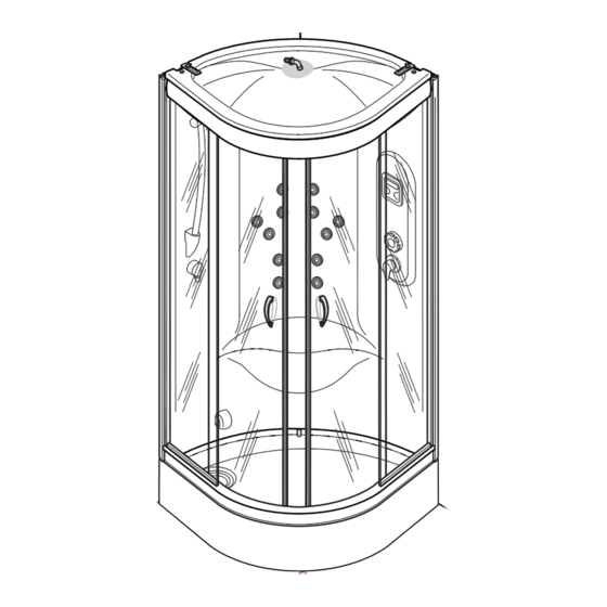
- Page 1 Assembly instructions and user Shower booth NEW BI-SIZE 70/80 x 90 RH - LH 80/85 x 80/85 90 x 90 GRUPPO GEROMIN S.r.l. reserves the right to make changes to the product at any time without giving any notice. Edition: 15/02/2019...
- Page 2 BEFORE CONNECTING THE APPLIANCE, THE INSTALLER MUST REQUEST THE DECLARATION OF CONFORMITY FOR THE PLUMBING AND ELECTRICAL SYSTEMS, AS REQUIRED BY LAW NO.46 OF 05/03/90. IN THE ABSENCE OF THIS DOCUMENTATION, HAFRO S.R.L. WILL DENY ANY RESPONSIBILITY FOR THE BUILDING OR SYSTEMS, WHERE ITS APPLIANCES ARE TO BE INSTALLED.
- Page 3 technical NEW BI-SIZE card 70/80 x 90 RH-LH 80/85 x 80/85 90x90 The minimum height of the tile covering, without projections, is the same as the height of the shower booth. Overall dimensions SYSTEMS Electrical specifications Caratteristiche idrauliche maximum water operating hydro connections...
- Page 4 NEW BI-SIZE Plumbing and electrical layout 70/80 x 90 RH-LH 80/85 x 80/85 90 x 90 C-D-D1 A - 1/2” cold water wall attachment. - 1/2” hot water wall attachment. Operating pressure: - MIN 150 kPa (1,5 bar) - MAX 300 kPa (3,0 bar) Hot water temperature: - MAX 60°C (140°F) C-D-D1 hose exit...
-
Page 5: Safety Zone
SAFETY ZONE INTRODUCTION WARNING: CHECK THE CONDITION OF THE PACKAGING AND THE GOODS UPON RECEIPT, ESPECIALLY IF THE PACKAGING SHOWS ANY VISIBLE DAMAGE. IF IT DOES, POINT Zone 1 THIS OUT TO THE TRANSPORTER IMMEDIATELY. THE MANUFACTURER DENIES ALL RESPONSIBILITY FOR TRANSPORT. - Page 6 HARDWARE FITTINGS KIT FOOT KIT (with shower tray) HARDWARE FITTINGS KIT FOR GLASS PANELS Pos. Q.ty Description Pos. Q.ty Description Screws 3,5x16 6954 Foot Screw-cover M10x20 ACMCAPPUC001 Screw 3,5x25 ACMDADI10005 HARDWARE FITTINGS KIT FOR SHOWER BOOTH (in main packaging) Screw 3,5x22 Seal cap Drainage column...
- Page 7 HARDWARE FITTINGS KIT BEARING KIT (in hardware fittings kit for glass panels) STEAM KIT Pos. Q.ty Description Pos. Q.ty Description Top bearing Boiler with electronics Screw-cover Silicone steam Screw hose M4x6 TUBA2SILICO1 Clip CN 15-25 Bottom bearing ACMFASCCN025 Screw-cover Connector RACCPGPL130010 Screw O-Ring...
- Page 8 FASE 1a INSTALLING THE SHOWER TRAY Remove the protective lm from the tray. Attach the drainage column to the shower tray, and fas - ten it ( g.2). Connect the exible drain hose “A3” (inside the man - ual pack) to the drainage column ( g.2).
-
Page 9: Panel Installation
PHASE 2 PANEL INSTALLATION Remove the protective film from the sponge seals “N” (fig.1) and insert them into the compensator profiles of the panel (fig.2). Cut away any extra parts (fig.3). PHASE 3 PANEL INSTALLATION Position the panel over the shower tray ( g.1), check that it is ush with the in - ternal edge of the shower... - Page 10 PHASE 4 ASSEMBLING THE GLASS PANELS Apply plenty of silicone to the given points (fig.1). Assemble the two glass panels with the top and bot - tom runners (fig.2) PHASE 5 ASSEMBLING THE GLASS PANELS Fasten together the as- sembled glass panels using the screws “C1”...
- Page 11 PHASE 6 ASSEMBLING THE GLASS PANELS Cut the seal cap “E1” into 4 pieces, the same length as the fixed glass panel (fig.1) and insert it into the inside of the closure (fig.2). Use liquid soap to make this operation easier. Apply plenty of silicone to the bottom part of the hollow on the vertical alu -...
- Page 12 PHASE 7 INSERTING THE CLOSURE Place the closure on the shower booth and lower it until the hollow of the lower profile fastens onto the shower tray profile. Make sure that the gasket “E1” , previously glued to the fixed profiles of the clo - sure, does not come free.
- Page 13 PHASE 9a ASSEMBLING AND INSERTING THE SLIDING DOORS Insert the top bearings “A2” into the top of the doors, fasten them with the screws “C2” and cover with the screw-cover cap “B2” (fig.1- Insert the bottom bearings “D2” into the bottom part of the doors in the same way and cover with the screw- cover cap “B2”...
- Page 14 PHASE 9b ASSEMBLING AND INSERTING THE SLIDING DOORS Fasten the sliding glass panels to the closures, first hooking on at the bottom of the door, and then, pulling upwards, hook on the top part (fig.5-6-7). Fasten the seal “H1” to the fixed glass panels (fig.8).
- Page 15 PHASE 10 ASSEMBLING THE TOP Remove the protective film from the top (fig.1) and insert it on the shower tray (fig.2). Fasten it at the ends with the screws “G” , the wash- ers “H” and the appropriate plates “E” (fig.3a) and in the middle with the screw “G”...
-
Page 16: Plumbing Connections
PHASE 11 PLUMBING CONNECTIONS For models with Turkish bath, take the electronic kit with boiler and attach it to the shower tray with two internal screws measuring 70x90 and external ones measuring 80x80 (fig.1). CONNECTIONS IN SE- QUENCE: Connect the hot and cold water outlets to the taps using two flexible hoses Only... - Page 17 PHASE 12 EQUIPOTENTIAL AND ELECTRICAL CONNECTION WHERE REQUIRED Before making the electri - cal connections, carefully read the notes on electri - cal safety. This appliance must be con - nected to the earth system of the building, in compli - ance with standard 64.8, 12 and 15 only for models with Only models...
-
Page 18: Fastening The Front Panel
PHASE 13 SHOWER BOOTH FASTENING BRACKETS Move the shower booth near the wall, check that the structure is straight and mark the holes for fastening and the top of the brackets (fig1). Move the shower booth away again and drill the holes with a 6 mm bit. - Page 19 Instructions for using the Taps Thank you for choosing a product, designed and manufactured to meet your well-being needs in the best way possible. MIXER HYDRAULIC CONTROLS FOR NEW BI-SIZE MOD. The SOUND stall is supplied with the mixer unit. The mixer control consists of two dials, the upper one (A) that serves as a diverter and, and the lower one (B) is used to adjust the water temperature and to open and close the water.
- Page 20 Only for version Junior Hello... Fig. 1: Pellicle Display ON/OFF General; Navigation key up; ON/OFF Turkish bath; Right navigation key; Radio FM; Left navigation key; Navigation key down; Allarm; 10 - Chromotherapy; Confirmation; Keyboard functions 1. ON/OFF General Pressing the button illuminates the backlight with the enabling of Turkish bath and radio functions.
- Page 21 Keyboard functionality (vers. junior) 2. ALLARM Pressing the key will bring the system into alarm mode by activatinga beep directly from the Radio Speaker. All active functions are deactivated and the display shows the alarm symbol (see figure 3). Pressing the button again turns off the alarm, the display it returns to the screen before the alarm.
- Page 22 Keyboard functionality (vers. junior) 1. White light and chromotherapy chromoterepia that is composed of energizing, relaxing, toning cycles the mode "Rainbow" (iris 42 colors) you can change the color of the LED lights by pressing the 4 and 6 keys. Figure 7: Menu light Figure 8: Menu light, active energizing cycle Figure 9: Down menu iris...
- Page 23 Cleaning The shower booth is made of material that makes for quick cleaning and which prevents possible build-up of bacteria on its surface. To clean the glass surfaces use specific products currently on the market. For all operations always use a soft cloth and use never abrasive pads.
- Page 24 GRUPPO GEROMIN S.r.l. Via I° Maggio n°5 (zona Industriale) 30029 San Stino di Livenza VE Tel. +39 0421 312249 / +39 0421 312250 http: www.gruppogeromin.com - email: info@gruppogeromin.com...
Need help?
Do you have a question about the NEW BI-SIZE Junior Series and is the answer not in the manual?
Questions and answers