Table of Contents
Advertisement
Advertisement
Table of Contents

Related Manuals for Datacom DM4170 Series


Summary of Contents for Datacom DM4170 Series
- Page 1 DM4170 CARRIER ETHERNET SWITCH INSTALLATION MANUAL 204.4308.03...
-
Page 2: Legal Notice
Installing the DM4170 LEGAL NOTICE Despite all precautions having been taken in the preparation of this document, DATACOM does not assume any responsibility for any possible errors or omissions, as well as no liability is assumed for damages resulting from the use of the information contained in this manual. -
Page 3: Contacts
DM4170 – Installation Manual Installing the DM4170 CONTACTS ECHNICAL UPPORT DATACOM provides a call center for technical support during the configuration and use of the equipment, in addition to providing technical assistance for repairs and maintenance. Email: suporte@datacom.ind.br Phone: +55 51 3933-3122 Website: http://www.datacom.ind.br/en/support... -
Page 4: Product Documentation
Release Notes – Informs users about new features, known bugs and hardware • compatibility. The availability of certain documents may vary depending on the type of product. Visit the DATACOM website to find related documentation or contact Technical Support for more information (see ONTACTS 204.4308.03... -
Page 5: Table Of Contents
DM4170 – Installation Manual Installing the DM4170 TABLE OF CONTENTS LEGAL NOTICE ..................................2 WARRANTY ....................................2 CONTACTS ....................................3 ................................3 ECHNICAL UPPORT .................................3 ENERAL NFORMATION PRODUCT DOCUMENTATION ............................4 TABLE OF CONTENTS ................................5 INTRODUCING THE PRODUCT’S INSTALLATION MANUAL ..............7 ..............................7 BOUT THIS MANUAL ..............................7 ARGET AUDIENCE ................................7... - Page 6 DM4170 – Installation Manual Installing the DM4170 4.1.2 Environment requirements......................... 22 4.1.3 Equipment requirements ..........................22 DM4170 P ..........................22 ACKAGE ONTENT ........................... 22 DENTIFYING THE RODUCT ..........................23 INCH RACK INSTALLATION PROTECTIVE GROUNDING ..................... 23 ONNECTING THE ................................24 ENTILATION ............................
-
Page 7: Introducing The Product's Installation Manual
DM4170 – Installation Manual Installing the DM4170 INTRODUCING THE PRODUCT’S INSTALLATION MANUAL BOUT THIS MANUAL This manual can be used for the DM4170 switches, providing information about the installation of this product line. The document focuses on the electrical and physical part, indicating the states of the equipment as well as the installation of its hardware. -
Page 8: Texts
DM4170 – Installation Manual Installing the DM4170 Icon Category Description people's health and the environment. For more information on where to discard equipment for recycling, contact your local dealer where the product was purchased. Table 1 – Icon Conventions A caution type notice calls attention to conditions that, if not avoided, may damage or destroy hardware. -
Page 9: Getting Started
DM4170 – Installation Manual Installing the DM4170 GETTING STARTED AFETY WARNINGS Before proceeding, carefully observe the following safety warnings: Before installation, the entire manual must be read carefully. If you have any questions, you should contact the authorized technical support. Pay attention to the safety instructions during the installation, operation and maintenance of this product. -
Page 10: Hardware Description
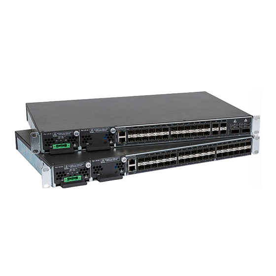
DM4170 – Installation Manual Installing the DM4170 HARDWARE DESCRIPTION This chapter describes the DM4170 line’s hardware features. DM4170 24GX+12XS Figure 3 - DM4170 24GX+12XS Views SLOT PSU1 (MAIN) SLOT PSU2 (BACKUP) USB Host Interface Serial Console Interface (RS-232) Gigabit Ethernet Management Interface (MGMT) LED Power (PWR) LED ALARM/FAIL... -
Page 11: Dm4170 24Gx+4Xs+2Qx
DM4170 – Installation Manual Installing the DM4170 DM4170 24GX+4XS+2QX Figure 4 - DM4170 24GX+4XS+2QX Views SLOT PSU1 (MAIN) SLOT PSU2 (BACKUP) USB Interface Console Serial Console Interface (RS-232) Gigabit Ethernet Management Interface (MGMT) LED Power (PWR) LED ALARM/FAIL 24 Gigabit Ethernet Ports (SFP) 4 10Gigabit Ethernet Ports (SFP+) 10 2 40Gigabit Ethernet Ports (QSFP+) 11 Front Panel Air Entry... -
Page 12: Serial Console Interface (Rs-232)
DM4170 – Installation Manual Installing the DM4170 LED PWR GREEN ON: Indicates that the source is powering the switch. • OFF: Power source failure or not powering. • OFF: Equipment operating normally, no failures or alarms detected. • ALARM/FAIL YELLOW/AMBER ON: Indicates that alarms were detected by the •... -
Page 13: Usb Interface Console
In the Microsoft Windows 10 the USB port is recognized and emulated as a serial port, this port can be accessed via a serial connection program. DATACOM does not provide the driver that will emulate or create a virtual serial port from the USB port. Due to security issues it is highly recommended that only use driver from trusted sources. -
Page 14: Data Interfaces
DM4170 – Installation Manual Installing the DM4170 Indicator Color Status Description LINK/ACT GREEN Link Down (inactive port) Link Up (active port) Blinking Data sending and/or receiving activity Port operating in 1000Base-T mode SPEED YELLOW Port operating in 10Base-T or 100Base-TX Table 7 - MGMT Interface LEDs NTERFACES 3.8.1... -
Page 15: Sfp+ Ethernet 10 Gigabit Optical Interfaces (10Gbase-X)
DM4170 – Installation Manual Installing the DM4170 Port operating at a rate lower than 1Gbps. Table 8 – Indicator LEDs for 1GbE SFP interfaces 3.8.2 SFP+ Ethernet 10 Gigabit Optical Interfaces (10GBase-X) The DM4170 versions have 4 or 12 10 Gigabit Ethernet optical interfaces depending on the model, all using an SFP+ connector. -
Page 16: Larm Nput And Utput
DM4170 – Installation Manual Installing the DM4170 Figure 10 - 40GbE QSFP+ LED ports 3.8.3.1 Indicator LEDs of 40 Gigabit Ethernet optical interfaces The convention to indicate the operation and mode of operation of the 40GbE QSFP+ interfaces are described in 10 –... -
Page 17: Psus And Ower Nputs
DM4170 – Installation Manual Installing the DM4170 For alarm output, the equipment uses a relay. In an alarm situation or when the switch is off, pin 7 (common) is short circuited with pin 8 (NC). When operating without alarms, pin 7 (common) will be short circuited with pin 6 (NO), while pin 8 (NC) will be isolated. - Page 18 DM4170 – Installation Manual Installing the DM4170 Figure 11 - PSU Panel 125 DC Figure 12 - PSU Panel 125 AC The equipment is de-energized through its power cable (s). The power outlet must be nearby and easily accessible. The electrical installation of the site should be protected by devices against short circuits.
-
Page 19: Pin Settings And Polarity
DM4170 – Installation Manual Installing the DM4170 3.10.1 Pin Settings and Polarity 3.10.1.1 PSU 125 AC 13 – AC P presents the pin assignment of the IEC IGURE OWER ONNECTOR SSIGNMENT 320/C14 connector for the power supply of the equipment. Figure 13 –... -
Page 20: Power Cables
DM4170 – Installation Manual Installing the DM4170 Figure 14 – DC Power Connector Pin Settings 3.10.2 Power Cables 3.10.2.1 PSU 125 AC The PSU 125 AC includes a 3-meter power cord in the standard female IEC 320/C14 for the NBR 14136 plug. 3.10.2.2 PSU 125 DC The PSU 125 includes a 3.5 meter DC power cable in the PP 1 mm... -
Page 21: Protective Grounding
DM4170 – Installation Manual Installing the DM4170 specifications of the country where it is installed. Step 3 Using a 1/8" screwdriver (number 0), screw the cable as shown below: • Figure 16 – Installing the cable to the TERMINAL BLOCK Step 4 Before the cable is powered, screw the connector with the cable installed on •... -
Page 22: Dm4170 Installation
DM4170 – Installation Manual Installing the DM4170 DM4170 INSTALLATION This chapter explains the procedures, recommendations, and attention related to installing the DM4170. REPARING THE INSTALLATION SITE Before installing the product, some care must be taken to guarantee that all steps can be followed correctly, thus ensuring proper installation. -
Page 23: Inch Rack Installation
DM4170 – Installation Manual Installing the DM4170 The DM4170 has a label on the rear side of the mechanics. It contains model information, product code and serial number. Check if there is any divergent information on the label regarding the information on the packaging. INCH RACK INSTALLATION The DM4170 was designed to be installed to 19-inch racks, occupying only 1U in height. -
Page 24: Ventilation
DM4170 – Installation Manual Installing the DM4170 Screw the connector to the switch using the same screw that was • Step 4 removed in step 1. Table 14 – Steps for the installation of the Protective Grounding ENTILATION The DM4170 switch ventilation airflow is provided by the inlets on the front and left sides of the equipment and through the outlets on the rear, as in 20 - DM4170. -
Page 25: Connecting To Power Supply
DM4170 – Installation Manual Installing the DM4170 4.7.2 Connecting to Power Supply After inserting the PSU 125 (s), connect the power supply according to the levels specified in TECHNICAL SPECIFICATIONS chapter. Each PSU slot has an independent power input; the DC PSUs have a front power source, while the AC PSUs have a power source at the rear panel aligned with its respective slot. -
Page 26: Installing And Removing Sfp/Sfp+/Qsfp+ Modules
INSTALLING AND REMOVING SFP/SFP+/QSFP+ MODULES This chapter describes how SFP/SFP+/QSFP+ modules must be installed and removed. It also informs about DATACOM guidelines for the cleaning and storage of modules and optical fibers. SFP (Small Form-factor Pluggable), SFP+ and QSFP+ modules are inserted into the switch's SFP, SFP+ and QSFP+ ports, operating as transceivers between the switch and the selected optical communication path. -
Page 27: Installing Sfp/Sfp+ Modules
DM4170 – Installation Manual Installing the DM4170 SFP/SFP+ M NSTALLING ODULES Follow the steps below to install SFP/SFP+ modules to the switch. Step 1 Remove the dust protection plug from the SFP/SFP+ slot where the module • will be inserted. Step 2 Insert the module into the SFP/SFP+ slot and press it until it is firmly inserted, •... -
Page 28: Removing Sfp/Sfp+ Modules
DM4170 – Installation Manual Installing the DM4170 SFP/SFP+ M EMOVING ODULES Before removing the optical cords, it is recommended that you check if there are labels on them that indicate to which equipment and port they should be connected, facilitating their identification later. In order to remove the modules, simply follow the same insertion instructions in reverse order: Step 1... -
Page 29: Accessing The Product
DM4170 – Installation Manual Installing the DM4170 ACCESSING THE PRODUCT ANAGEMENT THROUGH THE CONSOLE INTERFACE You can access the Command Line Interface (CLI) through the local console interface located on the left side of the product's front panel; to do so, simply connect a compatible console cable (710.0137.xx - supplied with the product) and run a terminal emulator such as Hyper Terminal or similar on a computer or laptop. - Page 30 DM4170 – Installation Manual Installing the DM4170 Only one account is accessed in the factory default setting of the DM4170 product line: admin User Password Description admin is an account with administrator privileges that admin admin allows the creation of the other accounts. Table 18 - Default account In either method, perform the following procedure: Step 1...
-
Page 31: Technical Specifications
DM4170 – Installation Manual Installing the DM4170 TECHNICAL SPECIFICATIONS NTERFACES Interfaces DM4170 24GX+12XS DM4170 24GX+4XS+2QX Console (RJ45) Ethernet Management (RJ45) USB Host (type A) USB Device (type B) 100Base-Fx/1000Base-X (SFP) 10/100/1000Base-T (RJ45) 1000Base-X/10GBase-X (SFP+) 40GBase-X (QSFP+) Table 20 - Interfaces DM4170 OWER UPPLY PECIFICATIONS... -
Page 32: Ower Upply And Utput
DM4170 – Installation Manual Installing the DM4170 OWER UPPLY AND UTPUT DM4170 24GX+12XS DM4170 24GX+4XS+2QX Typical PSU 125 DC consumption PSU 125 AC (Watts) Maximum PSU 125 DC 150W 140W consumption PSU 125 AC 150W 140W (Watts) PSU 125 DC 3.9A 3.6A Maximum current...
Need help?
Do you have a question about the DM4170 Series and is the answer not in the manual?
Questions and answers