
Subscribe to Our Youtube Channel
Related Manuals for Dectris MYTHEN2


Summary of Contents for Dectris MYTHEN2
- Page 1 User Manual MYTHEN2 Detector Systems Version 8 DEC TRI S Lt d. 5405 Baden- Da et t wi l 0/50 S wit zer la nd User Manual MYTHEN2 Detector Systems Version 8 www. dect r is. com...
- Page 2 Document Version V8 © Copyright 2020 DECTRIS Ltd 1/51 User Manual MYTHEN2 Detector Systems Version 8...
-
Page 3: Table Of Contents
Data Cable ........................23 6.7. Fixation Kit ........................25 Installing the Detector System....................27 7.1. Transport Considerations ....................27 7.2. Mounting the Detector System ..................27 7.3. Setting up the Computer ....................28 i/50 User Manual MYTHEN2 Detector Systems Version 8... - Page 4 12. Web Interface Update ......................48 13. Factory Reset ........................49 14. Temperature and Humidity Control ..................50 15. Cleaning and Maintenance ....................51 16. Appendix ..........................52 16.1. Referenced Documents ....................52 ii/51 User Manual MYTHEN2 Detector Systems Version 8...
- Page 5 Major update and documentation rework Document versioning system changed Contact information updated Figure 43 exchanged Module and DCS4 photos updated (screw lock cable and fixation kit) 04.09.2014 Old versions iii/51 User Manual MYTHEN2 Detector Systems Version 8...
-
Page 6: General Information
Should you have questions concerning the system or its use, please contact us via telephone, e-mail or fax. 1.2. Explanation of Symbols Symbol Description Important or helpful notice Caution. Please follow the instructions carefully to prevent equipment damage or personal injury. DC-current AC-current Ground Functional earth 1/50 User Manual MYTHEN2 Detector Systems Version 8... -
Page 7: Explanation Of Terms
DECTRIS is the sole owner of all user rights related to the contents of the manual (in particular information, images or materials), unless otherwise indicated. Without the written permission of DECTRIS it is prohibited to integrate the protected contents in this publication into other programs or other websites or to use them by any other means. - Page 8 DECTRIS reserves the right, at its own discretion and without liability or prior notice, to modify and/or discontinue this publication in whole or in part at any time, and is not obliged to update the contents of the manual. 3/51...
-
Page 9: Safety Instructions
Place the protective cover on the detector when it is not in use to prevent the detector from accidental damage. Opening the detector or the power supply housing without explicit instructions from DECTRIS will void the warranty. Do not install additional software or change the operating system. -
Page 10: System Description
*Frame rates up to 1000 Hz are possible only for the MYTHEN2 X-series (synchrotron applications). **In order to optimize signal-to-noise ratio, energies as low as 4 keV can be reached only with sensor geometry corresponding to 320 m thickness and 4 mm strip length (Table 1). -
Page 11: Basic Functionality
All DECTRIS detectors are based on the HPC technology. They are composed of a segmented silicon or CdTe sensor and the corresponding ASIC readout chip. In the case of MYTHEN2, the sensor is a one-dimensional array of silicon micro strips (channels). These are reverse biased, depleted pn-junctions that are processed in high-resistivity silicon. Each detecting unit (each strip) in such a silicon array is connected to its corresponding readout channel, designed with advanced CMOS technology. -
Page 12: Single Photon Counting
MYTHEN2 (micro strip detector). A hybrid channel of the MYTHEN2 detector comprises a charge-sensitive preamplifier (Figure 3) which amplifies the collected charge signal, generated in the sensor by the incoming X-ray. The preamplifier is followed by two shaping gain stages and a comparator with a globally adjustable threshold (comparator in Figure 3). - Page 13 However, if the X-ray energy is quite low compared to the electronic noise level, the threshold has to be set even lower, and therefore noise counts have to be taken into account. 8/51 User Manual MYTHEN2 Detector Systems Version 8...
-
Page 14: Detector Settings
X-ray energies. The MYTHEN2 software will always chose the optimal gain settings based on the threshold energy in use (Figure 5). For a given threshold energy, the gain is set as low as the electronic noise level allows to. This effectively suppresses noise counts from the electronics while keeping the shaping time as low as possible and maximizing the count rate of the detector. -
Page 15: Threshold Trimming
At high fluxes, a photon-counting system will not detect a certain fraction of photons due to pulse pile-up. The count rate behavior, i.e. the observed count rate as a function of incoming rate, of the MYTHEN2 detector can be modeled by an ideal, paralyzable detector, for which each photon leads to a dead-time of fixed length. -
Page 16: Mythen2 Detector Systems
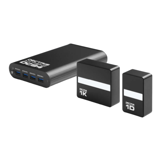
1000 Hz, and for R systems 25 Hz. Both R and X series are available in various sensor geometries (Table 2). This manual covers both systems (X, R) and all sensor geometries. For simplicity, in most cases MYTHEN2 R 1D figures will be used to represent the complete MYTHEN2 family of detectors. - Page 17 CHEMATIC OVERVIEW OF DETECTOR SYSTEM Connect only devices delivered by DECTRIS. to DCS4. Do not connect any other devices or USB devices to DCS4 - this might destroy the devices and the DCS4. “USB Warning: Only approved for DECTRIS modules. Connection of any other devices will result in damage.”...
-
Page 18: Technical Specifications
5.2. MYTHEN2 Detector Module The basic unit of the MYTHEN2 detector is a module, comprising 1280 or 640 silicon strips (channels). The detector module is mounted in a metal housing. The entrance window for X-rays is protected with a cover. - Page 19 Make sure that the cover is removed for detecting X-rays. Do not connect the detector module to any other device than the DCS4 delivered by DECTRIS. Connecting to different devices than the DCS4 might destroy the devices. “USB Warning: Only approved for DECTRIS modules. Connection of any other devices will result in damage.”...
-
Page 20: Detector Control System Dcs4
Weight [kg] excl. detector module and data cabeling 0.42 Operation voltage DCS4 [V DC] Power consumption of detector system consisting of DCS4 and 4 detector modules [W] Power supply external power supply 12 V DC / 5 A 15/51 User Manual MYTHEN2 Detector Systems Version 8... -
Page 21: Detector Dimensions And Connectors
Touching the Mylar foil can cause an electrical shock. 9: MYTHEN2 1D: D IGURE IMENSIONS OF THE MODULE HOUSING AND POSITIONS OF THE TAP HOLES FOR MOUNTING THE DETECTOR 16/51 User Manual MYTHEN2 Detector Systems Version 8... -
Page 22: Mythen2 1K
® Danger of electric shock. Do not touch the Mylar foil. The sensors behind the Mylar ® foil are operated at high voltages. Touching the Mylar foil can cause an electrical shock. 17/51 User Manual MYTHEN2 Detector Systems Version 8... -
Page 23: Detector Control System Dcs4
11: MYTHEN2 1K: D IGURE IMENSIONS OF THE MODULE HOUSING AND POSITIONS OF THE TAP HOLES FOR MOUNTING THE DETECTOR 6.3. Detector Control System DCS4 18/51 User Manual MYTHEN2 Detector Systems Version 8... - Page 24 12: D (DCS4): D DCS4: ( IGURE ETECTOR ONTROL YSTEM IMENSIONS AND POSITIONS OF THE TAP HOLES FOR MOUNTING THE DCS4. RONT PANEL ACK PANEL OWN AND ENDERING MODEL OF 19/51 User Manual MYTHEN2 Detector Systems Version 8...
-
Page 25: Connectors And Connecting Cables Dcs4
Functional earth of the detector system (M4 screw-in tap hole). Although the detector may be grounded via mounting bolts, the detector system can be grounded additionally via this functional earth connector to establish a defined grounding. 20/51 User Manual MYTHEN2 Detector Systems Version 8... -
Page 26: Dcs4 Front Panel
After completing the booting/initialization phase the LED becomes green again. +12V DC power connection +12V DC Use only the power supply delivered by DECTRIS. Reset switch for the DCS4. Pressing the RESET switch reboots the operating SwitchS system of the DCS4. This procedure may take a few minutes. - Page 27 The trigger output is on high level when the detector is making an exposure (“active high”). There are LEMO – BNC adapter available (LEMO ABF.00.250.CTA). Ask DECTRIS. support for details (see Section 1.1 for support). 22/51 User Manual MYTHEN2 Detector Systems Version 8...
-
Page 28: Power Supply
In case of a readout error, it becomes red. 6.5. Power Supply The MYTHEN2 detector system is delivered with a power supply. The output cable length is 1.8 m. The length of the input power cord is 2 m. The input cord connector is 8: P DCS4. - Page 29 Deforming connector pins by accident • Connecting detector module if DCS4 is powered off Use only the CE certified data and power cables delivered by DECTRIS. “USB Warning: Only approved for DECTRIS modules. Connection of any other devices will result in damage.”...
-
Page 30: Fixation Kit
6.7. Fixation Kit 15: F IGURE IXATION KIT IMENSIONS AND POSITIONS OF THE TAP HOLES DAPTER PLATE ASES AND RENDERINGS OF DAPTER PLATE ASES 25/51 User Manual MYTHEN2 Detector Systems Version 8... - Page 31 16: F DCS4 ( IGURE IXATION LATE AND TWO BASES UPPER AND LOWER ONE CHEMATIC DRAWING AND DCS4. IXATION PLATE INSTALLED ONTO 26/51 User Manual MYTHEN2 Detector Systems Version 8...
-
Page 32: Installing The Detector System
Control System (DCS4) and the detector module has a proper strain relief at both connectors. Use only the USB device cables delivered by DECTRIS. “USB Warning: Only approved for DECTRIS modules. Connection of any other devices will result in damage.” Do not use the detector system in vacuum. -
Page 33: Setting Up The Computer
7.3. Setting up the Computer To control the MYTHEN2 detector system, a computer with a LAN connection is required. The DCS4 is delivered with the fixed IP 192.168.0.90. The network card of the computer has to be configured to be in the same subnet as the DCS4, e.g. -
Page 34: Mythen2 Web Client
7.4. MYTHEN2 Web Client All graphics in this document show the Web Client as it appears in the case of one detector module connected to DCS4, but the description is valid for all MYTHEN2 detector configurations (1 to 4 modules). 7.4.1. Software Installation The only prerequisite to run the MYTHEN Web Client is a browser that supports JavaScript and WebSockets. -
Page 35: Acquisitions With Web Client
In order to start an acquisition, click the “Start” button. After the exposure has finished, the recorded counts are displayed as a function of channel number. Without an X-ray source, only very few counts due to background radiation like natural radioactivity or cosmic rays can be observed (Figure 20). 30/51 User Manual MYTHEN2 Detector Systems Version 8... - Page 36 (Figure 21). The data can be downloaded as compressed ZIP file by pressing the “Save” button (due to technical limitations the saved file may not have a proper file extension when using older versions of Firefox). 21: T IGURE HE ACQUISITION ACCORDION 31/51 User Manual MYTHEN2 Detector Systems Version 8...
-
Page 37: Customizing The Acquisition Settings
Web Client Settings accordion. Two sliders for these parameters will become available in the main panel, as presented on Figure 23 and Figure 24. 23: E IGURE NABLING THE EXPERT MODE 24: S IGURE LIDER FOR ADJUSTING THE RAY ENERGY AND THE THRESHOLD ENERGY 32/51 User Manual MYTHEN2 Detector Systems Version 8... -
Page 38: Complete Documentation
7.4.5. Complete Documentation The complete documentation of the Web Client can be found in the “Help” accordion on the right (Figure 25). 25: A IGURE CCESS TO THE FULL DOCUMENTATION 33/51 User Manual MYTHEN2 Detector Systems Version 8... -
Page 39: Changing Network Settings
By clicking on “Edit network settings” you will be prompted to enter your username and password. The username is “admin” and the password is given on the system information sheet (Figure 27). 34/51 User Manual MYTHEN2 Detector Systems Version 8... - Page 40 DHCP), the IP, the net mask, broadcast, the gateway and the MAC address. After making your changes and checking that all settings are correct, press the submit button. In order to activate the changes, the DCS4 has to be power-cycled. 35/51 User Manual MYTHEN2 Detector Systems Version 8...
-
Page 41: Triggering And Gating
Detector Control System (DCS4) and labeled EXT IN (for technical details, please see Section 4, MYTHEN2 detector system, and Section 5, technical specifications). -
Page 42: Internal Trigger
, before starting the exposure of the first frame. 29: S IGURE INGLE TRIGGER MODE In single trigger mode, the following equation must be met: t > 1/ f for acquisitions with more after than one frame. 37/51 User Manual MYTHEN2 Detector Systems Version 8... -
Page 43: Activating The Trigger Mode
When using the Socket Interface, the “Single” trigger mode can be activated with the command “-trigen 1”. 31: T EXT IN EN OUT IGURE SIGNAL BLUE AND THE SIGNAL GREEN DURING AN ACQUISITION 38/51 User Manual MYTHEN2 Detector Systems Version 8... -
Page 44: Trigger Level And Time Jitter
(Figure 33, Figure 34). When using the Socket Interface, the delay before the frame can be set with the command “-delbef ˂time˃”. 33: D IGURE ELAY TIME AFTER WHICH THE EXPOSURE IS STARTED 39/51 User Manual MYTHEN2 Detector Systems Version 8... -
Page 45: Trigger Signal And Multiple Readouts
(Figure 36). For a detector operating in 24-bit mode, the minimal delay given by the readout time of the ASICs is 89 µs. If a shorter delay is set in the Web Client or the Socket Server, the actual delay between two frames is equal to this readout time. 40/51 User Manual MYTHEN2 Detector Systems Version 8... -
Page 46: Continuous Trigger
Figure 40. The corresponding EXT IN and EN OUT signals are depicted in Figure 37: P IGURE RINCIPLE OF CONTINUOUS TRIGGER MODE 38: C IGURE ONTINUOUS TRIGGER MODE 39: M IGURE EASUREMENT WITH READOUTS EACH 41/51 User Manual MYTHEN2 Detector Systems Version 8... - Page 47 SIGNAL FOR TRIGGERED READOUTS WITH A DELAY TIME OF When using the Socket Interface, the “Continuous” trigger mode can be activated with the command “- conttrigen 1”. The number of frames is set with the command “-frames ˂n˃”. 42/51 User Manual MYTHEN2 Detector Systems Version 8...
-
Page 48: Gating/ External Enable
If more than one readout should be gated, the number of frames has to be changed to the required number of frames (Figure 44). 44: N IGURE UMBER OF FRAMES CAN BE ADAPTED IN THE MAIN PANEL ON THE LEFT 43/51 User Manual MYTHEN2 Detector Systems Version 8... - Page 49 Since the external gating signal at the EXT IN connector is not synchronized with the internal clock frequency of the detector system which is used for sampling the gating signal, a time jitter of maximal 20 ns for the beginning and finishing of the acquisition occurs. 44/51 User Manual MYTHEN2 Detector Systems Version 8...
-
Page 50: Bad Channels
DCS4 has to be power-cycled. 45: M IGURE ASK TO ADD OR REMOVE BAD CHANNELS FROM THE BAD CHANNEL FILES NLY ONE CHANNEL CAN BE REMOVED OR ADDED AT THE SAME TIME 45/51 User Manual MYTHEN2 Detector Systems Version 8... -
Page 51: Firmware Update
2. Open a browser on your PC. 3. Enter the IP address of the DCS4 system. By default the MYTHEN2 systems are delivered with the IP 192.168.0.90. You should now see a screen like the one shown on Figure 46. - Page 52 46: L DCS4 IGURE OGIN TO THE VIA YOUR WEB BROWSER 47/51 User Manual MYTHEN2 Detector Systems Version 8...
-
Page 53: Web Interface Update
ARNING SHOWN AFTER WEB INTERFACE UPDATE In case of problems, the DCS4 can be set back to factory settings with help of the delivered micro-SD card. System reset takes five to ten minutes. 48/51 User Manual MYTHEN2 Detector Systems Version 8... -
Page 54: Factory Reset
4. After a few minutes, the LED stops blinking and the system shuts down. 5. Power off the DCS4. When booting the next time, the system will come up with its factory settings. 49/51 User Manual MYTHEN2 Detector Systems Version 8... -
Page 55: Temperature And Humidity Control
14. Temperature and Humidity Control The MYTHEN2 Module has combined temperature and humidity sensor. The recommended temperature range for operation is shown in Table 10. 10: A ABLE MBIENT CONDITIONS Condition Range Operating temperature 18°C to 28°C Operating humidity < 75% RH @ 23°C Storage temperature 15°C to 40°C... -
Page 56: Cleaning And Maintenance
If it becomes dirty or is damaged, please contact DECTRIS technical support The MYTHEN2 detector system has been designed for the detection of X-rays from synchrotron sources or laboratory sources. For other applications, please contact DECTRIS. for additional information. -
Page 57: Appendix
16. Appendix 16.1. Referenced Documents following documents available through DECTRIS. Homepage (https://www.dectris.com/support/manuals-docs/overview). 11: R ABLE EFERENCED OCUMENTS Term Description Socket Interface Specifications Socket_Interface_Spec-MYTHEN2-V4p1p0_V1.pdf 52/51 User Manual MYTHEN2 Detector Systems Version 8...
Need help?
Do you have a question about the MYTHEN2 and is the answer not in the manual?
Questions and answers