Advertisement
Quick Links
Advertisement

Related Manuals for Dynascan DS551DR4


Summary of Contents for Dynascan DS551DR4
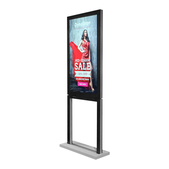
- Page 1 DS551DR4 INSTALLATION GUIDE V 3.2...
- Page 2 Layout of DS551DR4 & Stand INSTALLATION GUIDE 824.3 62.7 1000 nit 3000 nit IR receiver IR receiver 81.2 254.4...
- Page 3 Specifications – DS551DR4 INSTALLATION GUIDE POWER PANEL LCD Panel Type 54.64 inches IPS LCD Power Supply Internal Rated Voltage 100V ~ 240V, 50Hz/ 60Hz Native Resolution 1920 x 1080 Power On Mode 270(typ), 420(max) Backlight Power Saving Mode < 1W...
- Page 4 Specifications – DS551DR4 INSTALLATION GUIDE USER INTERFACE I/O PORTS HDMI Language English RS-232 Proof of Image Retention Dimming Control (DCR) RJ-45 On/ Off Schedule Ambient Light Sensor Total Turn-On Time ENVIRONMENT Internal Temperature Sensor Operating Temperature 0°C ~ 45°C Network Control...
- Page 5 Read this before you mount the display on the stand INSTALLATION GUIDE We recommend for two people working together to mount the system. Follow local regulations. The stand must be installed by qualified personnel, in accordance with professional assessment.
- Page 6 Packaging – DS551DR4 LCD INSTALLATION GUIDE DS551DR4 LCD Height 937mm Width 1456mm Depth 186mm Weight 49kg (set)/ 54kg (package)
- Page 7 Packaging – DS551DR4 LCD INSTALLATION GUIDE Pull handles to remove Open the lid, take covers out...
- Page 8 Packaging – DS551DR4 LCD INSTALLATION GUIDE Remove the lid Power Cord...
- Page 9 Packaging – DS551DR4 LCD INSTALLATION GUIDE Lay the EPE flat on the floor or your work station. Remote Control Batteries M3x4 x2 (AAA x 2) Cat. 5 Cable x2 RS232 1800mm 9 Pin Female – Female, 1800mm...
- Page 10 Packaging – DS551DR4 LCD INSTALLATION GUIDE Take the display out, flat on the EPE which you have prepared We recommend for two people working together to move the display out. Use the lifting handles to help you carry the display easily.
- Page 11 Packaging – DS551DR4 Stand INSTALLATION GUIDE DS551DR4 Stand Height 1048mm Width 998mm Depth 398mm Weight 35kg (set)/ 40.5kg (package)
- Page 12 Packaging – DS551DR4 Stand INSTALLATION GUIDE Pull handles to remove Open the cover and remove EPE...
- Page 13 Packaging – DS551DR4 Stand INSTALLATION GUIDE Take the cable cover out The cover is not mount yet. Bracket x1 Accessory Bag M6x15, countersunk x12 spring washer x12 flat washer x12 M4x8 x2 M3x4 x2...
- Page 14 Packaging – DS551DR4 Stand INSTALLATION GUIDE Remove the stand Remove the EPE and connecting kit A & B are inside.
- Page 15 Step 1 Mount connecting kits INSTALLATION GUIDE Insert the connecting kit from underneath the display. Connecting kit B with mark V Connecting kit A with mark W...
- Page 16 Step 2.1 Fasten connecting kits INSTALLATION GUIDE Tighten the connecting kit on both sides of the display. (M6x15) spring washer flat washer...
- Page 17 Step 2.2 Fasten connecting kits INSTALLATION GUIDE You can see the other side of the display and Connecting kit B with the mark V. You can see one side of the display and Connecting kit A with the mark W.
- Page 18 Step 3 Fasten the bracket INSTALLATION GUIDE Tighten the bracket on the bottom of the display, viewed on underneath. (M4x8)
- Page 19 Step 4 Remove covers from the stand INSTALLATION GUIDE Press the strip down and it will lift up. Remove the cover strip from the bottom of the stand. Loosen four screws to remove covers. (M5x10)
- Page 20 Step 5 Remove two covers INSTALLATION GUIDE Remove two covers from the bottom of the stand.
- Page 21 Step 6 Remove covers from the stand INSTALLATION GUIDE Slide inner covers up (1cm above the stand). Remove both sides of inner covers from the stand. Slide outer covers up (1cm above the stand). Remove both sides of outer covers from the stand.
- Page 22 Step 7 Secure the Stand INSTALLATION GUIDE Affix the stand to the ground or your customized platform. • Fasten the stand in a secure manner ensuring that your customized platform ’s structure and mounting hardware is sufficient to support the weight of display and stand. •...
- Page 23 Step 8 Hits for your installation INSTALLATION GUIDE indicate the side of 3000 nit display indicate the side of 1000 nit display ...
- Page 24 Step 9 Lift display onto stand INSTALLATION GUIDE Accessed the display from the sides of the stand. Put the display down smoothly and enters the slots properly. We recommend for two people working together to lift the display. Do not let go of the monitor before it is securely placed and fasten on the stand. Tighten the screws and check that the display is properly fastened.
- Page 25 Step 10 Fasten the monitor INSTALLATION GUIDE Tighten the screws on each side. (M6x15) spring washer flat washer...
- Page 26 Step 11.1 Connect & Organize pre-mounted cables INSTALLATION GUIDE Stretch out the cables in the channel on bottom of the display, and place them as illustrated. (Refer to the Step 11.2) LAN-2 1000 nit HDMI-2 Vent Switch Vent USB-2 RS232 USB-1 A/C IN HDMI-1...
- Page 27 Step 11.2 Connect & Organize pre-mounted cables INSTALLATION GUIDE The power cord through the hole of stand’s inner cover and connect to the display. If you need, route the cables (RS-232, LAN, USB, HDMI) down as above (power cord) illustrated, and put them in two sides of the stand.
- Page 28 Step 12 Mount covers of the stand INSTALLATION GUIDE Place inner covers back to both sides of the stand (1cm above the stand). Slide the covers down. Place outer covers back to both sides of the stand (1cm above the stand). Slide the covers down.
- Page 29 Step 13 Remove handles from the display INSTALLATION GUIDE Remove handles from each side of the display.
- Page 30 Step 14 Mount covers of the stand INSTALLATION GUIDE Place covers back to both sides of the display (1cm above the display). Slide the covers down. Tighten one screw on each side. (M3x4)
- Page 31 Step 15 Mount Covers of the Stand INSTALLATION GUIDE Mount two covers back to the bottom of the stand. If you need, mount power strip, player or other devices before mount covers of the stand.
- Page 32 Step 16 Mount Covers of the Stand INSTALLATION GUIDE Tighten four screws back to mount covers. (M5x10) Mount the cover strip back to the stand.
- Page 33 Step 17.1 Mount cable cover INSTALLATION GUIDE Mount cable cover back to the stand. Check the installation direction that there's a hole on the cable through cover which is for switch control.
- Page 34 Step 17.2 Mount cable cover INSTALLATION GUIDE Tighten one screw on each side. (M3x4)
- Page 35 Step 18 Accomplish the Installation INSTALLATION GUIDE...
Need help?
Do you have a question about the DS551DR4 and is the answer not in the manual?
Questions and answers