Myenergi Zappi Series Operation & Installation Manual
Ac ev charger
Hide thumbs
Also See for Zappi Series:
- Operation & installation manual (37 pages) ,
- Operation & installation manual (48 pages)
Table of Contents
Advertisement
MODELS:
Zappi-207UW
ZAPPI-207UW-A
ZAPPI-207TW
ZAPPI-207TW-A
ZAPPI-222UW
ZAPPI-222UW-A
ZAPPI-222UB
ZAPPI-222UB-A
Rev 1.4 May 2020 – ENGLISH
ZAPPI-207UB
ZAPPI-207UB-A
ZAPPI-207TB
ZAPPI-207TB-A
ZAPPI-222TW
ZAPPI-222TW-A
ZAPPI-222TB
ZAPPI-222TB-A
Advertisement
Table of Contents

Subscribe to Our Youtube Channel
Related Manuals for Myenergi Zappi Series


Summary of Contents for Myenergi Zappi Series
- Page 1 MODELS: ZAPPI-207UW ZAPPI-207UB ZAPPI-207UW-A ZAPPI-207UB-A ZAPPI-207TW ZAPPI-207TB ZAPPI-207TW-A ZAPPI-207TB-A ZAPPI-222UW ZAPPI-222TW ZAPPI-222UW-A ZAPPI-222TW-A ZAPPI-222UB ZAPPI-222TB ZAPPI-222UB-A ZAPPI-222TB-A Rev 1.4 May 2020 – ENGLISH...
- Page 2 Safety........................................3 Overview........................................4 Controls & Indicators.................................... 6 Display........................................7 Status Screens....................................... 9 Charging Modes..................................... 11 Manual Boost......................................12 Smart Boost......................................12 Boost Timer......................................14 Lock Function......................................15 Main Menu......................................16 Advanced Menu....................................19 eSense........................................24 Linking Devices....................................25 Electrical Installation..................................30 Wiring........................................
- Page 3 We are grateful for any suggestions for improvement and notices of errors in the operating instructions. myenergi zappi, myenergi eddi, myenergi harvi and myenergi hub are registered trademarks of myenergi Ltd. operation and installation manual...
- Page 4 Tethered units Untethered units unit with EV cable and connector attached. unit. 1 x Cable wall guard 1 or 3 x CT Clamps 1 or 3 x CT Clamps (1 x single phase units / 3 x three-phase units). (1 x single phase units / 3 x three-phase units). 1 x Mounting template.
- Page 5 operation and installation manual...
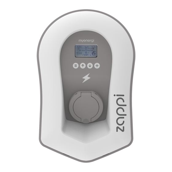
- Page 6 Display Graphical LCD display with LED backlight Backlight can be activated by tapping the unit. • Front fascia Removable fascia for installing and servicing. Tethered Charging Cable if 6.5 meter cable with a Type 2 plug or Type 2 socket with locking system applicable for non tethered models.
- Page 7 Import / Export Power The power being either imported or exported from or to the grid (kW). The direction of the arrows indicate if the property is currently importing power (left) or exporting power (right) The size of the arrows is proportionate to the level of power being imported / exported, When the property is neither importing or exporting power the figure will be 0.0kW and there will no animated arrows.
- Page 8 House Consumption – Not Importing Charge Mode = FAST House Consumption – Importing Charge Mode = ECO Solar Generation Power Charge Mode = ECO+ Device – Normal On the three phase the number in the Wind Generation Power icon indicates whether the EV is charging with a single phase or all three phases.
- Page 9 The EV is not connected to In this example the last charging session delivered 20.8kWh of energy to the EV and 80% of that energy came from the solar panels. is waiting for sufficient surplus power from the microgeneration system. This screen will be shown in ECO+ mode as it's only in this mode that charging will stop if there is not enough surplus power.
- Page 10 The EV is charging. In this example the car is charging in ECO+ mode at 1.6kW, there is no import or export from the grid (0.0kW) and the EV battery has charged by 8.9kWh since the car started. The EV is fully charged. The charge energy used during the last charge is displayed at the bottom right (20.0kWh in this case) and the 'green contribution' is also shown (40% in this example).
- Page 11 has three different charging modes which can be selected simply by pressing the buttons when the main screen is showing. The charge mode can be changed before or during a charge. FAST ECO+ Regardless of the charge mode used, all of the surplus electricity is used but special charge modes limit the amount of grid electric used.
- Page 12 The Manual Boost function can only be used when charging in ECO or ECO+ mode. When boosting, the charge rate is set to maximum (just like FAST mode), until a set amount of energy has been stored in the EV's battery. After which, will revert back to ECO or ECO+ mode.
- Page 13 When charging in ECO or ECO+ mode, press until SMART BOOST is shown. The SMART BOOST icon will show including the target time and the pre-set energy amount (7.00am and 17kWh respectively, in this example screen shot). will then test the EV for a few seconds, to determine the maximum charge rate.
- Page 14 When using ECO or ECO+ charge modes, can be programmed to 'boost' the current charge at certain times. When boosting, the charge rate is set to maximum (just like FAST mode), regardless of the amount of available surplus power. This means that power may be drawn from the mains grid supply during boost times. There are four editable time slots which can be set to operate for certain days of the week.
- Page 15 can be locked from unauthorised operation. The Lock Function requires a PIN number to be entered before the unit can be operated. The lock can be set to be active Only when the EV is plugged in. – Only when the EV is unplugged. –...
- Page 16 Main Menu Options Description Charge Log… Today… Yesterday… Week… Month… Log of charge sessions Year… Total… Custom Date… Event Log… Today… Yesterday… Week… Log of events Custom Date… WCS… Readings… READINGS Status: Mode: Current status and charging mode of the unit Exporting: Power being exported or imported, from or to the grid respectively Importing:...
- Page 17 Main Menu Options Description Information INFORMATION Status: Status of the unit … Serial No: Serial number of the unit Firmware version installed in the unit Firmware: Assembled: Factory assembly date Cal Date: Calibration changed date Power Fail: Time and date of last supply failure INFORMATION Grid Sensor: Grid current sensor source...
- Page 18 Main Menu Options Description before zappi reset) Other Time & Time: Set current time in 24 hour format Settings… Date… Set date in Format (see below) Date: Format: Sets the date format Auto DST: Automatic Daylight Saving Time adjustment Zone: Set zone for Daylight Saving Time Update from Cloud: Sets time automatically providing a hub is...
- Page 19 Advanced Menu Options Description Supply Grid… Device… Phase:(single phase) Set the supply phase to use for this device – see Advanced Phase Rotation:(three phase) Settings (page 20) for more information Phase Return: Set the phase wired into the “Neutral” input terminal. Device Limit: Set the maximum available supply current to be drawn by the –...
- Page 20 Advanced Menu Options Description Keeps ready to restart charge after charge is complete – Infinite PWM: this is needed on some EV's when the user wants to preheat the vehicle in morning Menu Passcode... The code required to access the Advanced menu System…...
- Page 21 – Sets the maximum current that the will draw (including when boosting and FAST mode). This is useful if the supply current is limited, for instance, if is connected on a 16A circuit instead of a 32A. – Sets the limit that can be drawn from the grid connection (i.e. the maximum import current or the main fuse rating). Example: A property may have a grid supply limit of only 65A, several appliances are on, the property is consuming 12kW (52A) to supply these appliances and the user wants to charge in FAST mode.
- Page 22 Setting Function description There is no battery system installed. None Will limit the output of the (except when boosting), to prevent unwanted draining of an Limit to Gen AC coupled battery system. This setting does not require a CT to monitor the battery, but does need a CT to monitor the solar/wind generation.
- Page 23 CT Type Description pointing away from it. Monitors Solar PV or Wind generation that is combined with a DC-coupled battery. Gen & Battery Monitors any load, for example a washing machine or the lighting circuit. Monitor This setting can also be used to limit current drawn by devices on a particular circuit which includes other loads.
- Page 24 Group Limit example Additional CT installed CT config (all devices) Limit current drawn by two None; only the internal CTs are used. CTIL Type: Internal devices that are on the same 32A Group: IL1 supply. Group Limit: 32A Limit current drawn by an One CT is clipped around Live of the 32A supply and Type: Monitor device that is fed from a 32A supply...
- Page 25 Up to six devices can be wirelessly linked together. By linking devices, you can use more of your own energy or have more control and visibility. Devices available now are: A microgeneration energy diverter that uses surplus power to heat water or rooms rather than exporting to the grid.
- Page 26 Most device types have settings which can only be changed via the Linked Devices menu. For example, have a settings for priority and has settings to configure its CT inputs (see Device Priorities page 26). The device settings are accessed through the Linked Devices menu; select Devices then select the appropriate device and press to bring up the devices' settings screen.
- Page 27 Grid CT – the device has a Grid CT configured (there should be only one) Master – the device is the controlling device in the network Boost – the device is currently boosting Max – the device is at maximum output power Min –...
- Page 28 When installing and wiring the care should be taken to maintain the IP rating of the unit. Ensure that the grommets and bungs provided are fitted, the O-ring behind the cover is seated correctly and that the electricity cable is fitted using an appropriate size and type of gland. Carefully remove fascia from the by pressing the 2 If installing a tethered...
- Page 29 Using template mark mounting holes. To maintain the IP rating of the unit you will need to add bungs (provided) to the holes not used. Use top and 2 bottom holes left/right for brick use 2 vertical holes if mounting to a stud wall or joist. Using the fixing kit provided secure unit to the wall Ensure O-ring is present and sits neatly into its channel.
- Page 30 Warnings WARNING! An electric shock can be fatal; electrical connection work may only be carried out by a competent person The earth conductor must be correctly installed and reliably connected This device must be equipped with an over-current protection device of maximum 32 Amps (B32) The single phase should be connected to a 230V/240V nominal AC supply.
- Page 31 Insert mains cable through the installed cable gland (if not already done so) strip back outer sheath ensuring all cables reach the terminal blocks shown above (leaving a little excess) strip back all coloured cables approx 10mm, if using hard wired CT clamps now is the time to insert these too (we recommend a specialist cable gland that can accommodate multiple cables whilst still maintaining IP integrity).
- Page 32 CT1 CT2 CT3 For 3 phase installations without the need for For 3 phase installations with the need for 1 or more hardwiring an external CT please use the above external / additional CT’s please use the above diagram. diagram. Positive (+) = Red Negative (-) Black Earth = Green / Yellow cable...
- Page 33 operation and installation manual...
- Page 34 Installation Current Transformers (CTs) are used to measure current at various places of the installation. For example, the Grid connection point, the solar/wind inverter or a static battery system. Installation of a CT to monitor the Grid connection point is required for ECO modes, Other CTs are optional and can be purchased separately.
- Page 35 If using a 3 phase system a CT sensor (supplied) needs to be clipped around each live tail. The positioning of the Grid CT sensor is crucial, please take note of the following when deciding where best to install the sensor: ✔...
- Page 36 Grid CT Only ONE Grid CT per phase (check for only one ~ symbol in Linked Devices Info). • Located to ‘see’ ALL import and ALL export current (i.e. always upstream of any junction box). • Arrow pointing in direction of import (e.g. towards consumer unit if on Live cable). •...
- Page 37 Offer cover to the enclosure ensuring all cables are neatly Add fascia to the enclosure cover of the inside the unit. shown. Ensure O-ring (seal) is firmly placed into the channel. Secure cover to unit using the 8 screws removed earlier (Torque setting = 1.2Nm).
- Page 38 CTs can be also used to limit the current drawn by devices to avoid overloading circuits; this is sometimes referred to as load balancing. There are four different ways to limit current and they can be used alone or combined for more complex situations.
- Page 39 device if wireless measurement is required. This CT should be clipped around the live or neutral cable of battery inverter. (CT should be reversed if clamped on the neutral cable) During the setup process it will be necessary to change the setting for the appropriate CT to AC Battery; refer to CT Config (page 22) .
- Page 40 has a number of protection features built into the device to make it safe and simple to install. The RCD (Residual Current Device) will trip the output from if there is an electrical fault to ground. The RCD is similar to the protective devices found in most domestic consumer units (the “fuse box”) but the standards for electric vehicle charging require additional protection for small DC leakage currents.
- Page 41 will also isolate the supply to the EV if it detects a problem with the electricity supply voltage. The nominal supply voltage is 230V but will trip the output if the measured voltage is more than 10% above or below this level for five seconds.
- Page 42 Symptom Cause Solution Display is blank - There is no power to the - Check for correct supply voltage at the unit supply screw terminals (220 - 260V In ECO+ mode, the charge - Grid Sensor incorrectly - Check the grid sensor is connected to does not start, the display is installed CT1 or CT2 terminals of the...
- Page 43 If any of the following fault messages are displayed, follow the action described. However, if the problem persists, stop using and call your installer or your local technical support. Displayed Message Description Action has detected an unknown EV cable (untethered units only) will automatically retest the cable Make you are using genuine IEC 62196-2 after 5 seconds.
- Page 44 Please register your new devices at https://myenergi.com/product-registration/ operation and installation manual...
- Page 45 Performance Mounting Location Indoor or Outdoor (permanent mounting) Charging Mode Mode 3 (IEC 61851-1 compliant communication protocol) Display Graphical backlit LCD Front LED Multicolour, according to charge status, current and user setting Charging Current 6A to 32A (variable) Dynamic Load Balancing Optional setting to limit current drawn from the unit supply or the grid Charging Profile 3 charging modes: ECO, ECO+ and FAST...
- Page 46 Charging Modes Charge power is continuously adjusted in response to changes in generation or power consumption elsewhere in the home. Charging will continue until the vehicle is fully charged, even if power is drawn from the grid. ECO + Charge power is continuously adjusted in response to changes in generation or power consumption elsewhere in the home.
- Page 47 If you experience any issues with your during or post installation, please contact our technical support team: support@myenergi.com 0333 300 1303 Mon-Thu 9.00am – 5.00pm Fri 9.30am – 5.00pm Our experienced engineers will be pleased to assist and to help solve your issues over the phone.
- Page 48 Please used these pages to record the details of your devices and how they are configured Date Installed: _____________________________ Installer Name / Contact:_________________________________________________________________ Master Device?: Y / N CT Connections – If external CT’s are connected to your what are the CT’s measuring? CT1: _____________________________________ CT2: _______________________________________ CT3: _____________________________________...
- Page 49 Make sure you register your new www.myenergi.com/product- registrat i on and also have a look at the Designed and manufactured in the UK by myenergi Ltd, Church View Business Park, Binbrook, Lincolnshire, LN8 6BY, UK T: +44 (0)333 300 1303 E: sales@myenergi.com W: myenergi.com...
Need help?
Do you have a question about the Zappi Series and is the answer not in the manual?
Questions and answers