Table of Contents
Advertisement
Quick Links
EN50155
Switch
Q
I
I N D U S T R I A L
uick
nstallation
Rack-Mount
Introduction
TRGPS-9084GT-M12X-BP2-MV is a managed Gigabit Ethernet switch with
8 Gigabit PoE-enabled ports and 4 Gigabit non-PoE ports in M12
connector. The non-PoE ports act as two sets of bypass ports to ensure
constant network connectivity when power outage or node failure occurs.
The switch supports various Ethernet redundancy protocols such as O-Ring
, O-Chain and MSTP (RSTP/STP compatible) to protect your mission-
critical
applications
from
network
malfunctions. With EN50155 compliance and M12 connectors, the
device is a perfect choice for rolling stock applications.
Package Contents
The device is shipped with the following items. If any of these items is
missing or damaged, please contact your customer service representative
for assistance.
Contents
Pictures
TRGPS-9084GT-M12X-BP2-MV
Console Cable
Rack-mounted kit (L&R)
CD
QIG
Preparation
Before you begin installing the device, make sure you have all of the
package contents available and a PC with Microsoft Internet Explorer 6.0 or
later, for using web-based system management tools.
Safety & Warnings
Elevated Operating Ambient: If installed in a closed environment, make sure
the operating ambient temperature is compatible with the maximum
ambient temperature (Tma) specified by the manufacturer.
Reduced Air Flow: Make sure the amount of air flow required for safe
operation of the equipment is not compromised during installation.
Mechanical Loading: Make sure the mounting of the equipment is not in a
hazardous condition due to uneven mechanical loading.
Circuit Overloading: Consideration should be given to the connection of the
equipment to the supply circuit and the effect that overloading of the circuits
might have on overcurrent protection and supply wiring. Appropriate
consideration of equipment nameplate ratings should be used when
addressing this concern.
Q I G
TRGPS-9084GT-M12X-BP2-MV
TRGPS-9084GT-M12X-BP2-MV
G
uide
Dimension
interruptions
or
temporary
Number
Panel Layouts
1
72~110VDC
N.C.
1
Power
Relay
6
7
1
1. Reset button
2. Power status LED
3. R.M. status LED
4. Ring status LED
1
5. Fault LED
6. Power connector
7. Relay output port
8. Console port
1
Installation
Rack-mounting
Step 1: Install left and right front mounting brackets to the switch using 4 M3 screws on each side
provided with switch.
Step 2: With front brackets orientated in front of the rack, nest front and rear brackets
together. Fasten together using remaining M4 screws into counter sunk holes.
Step 3: Fasten the front mounting bracket to the front of the rack.
1907-2-29-TRGPS9084GTM12XBP2MV-1.0
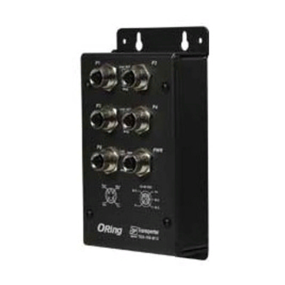
Front View
3
2
12
G1~G8
G1~G12
G9~G12
Power
Speed
Speed
1.BI_DA+/PoE Vout+
5.BI_DD+
1.BI_DA+
5.BI_DD+
Failure
PoE
2.BI_DA- /PoE Vout+
6.BI_DD-
2.BI_DA-
6.BI_DD-
Bypass
PWR
TRGPS-9084GT-M12X-BP2-MV
3.BI_DB+/PoE Vout-
7.BI_DC-
3.BI_DB+
7.BI_DC-
LNK/ACT
LNK/ACT
G9
G10
G11
G12
4.BI_DB- /PoE Vout-
8.BI_DC+
4.BI_DB-
8.BI_DC+
R.M
4
Ring
Fault
Reset
Console
G1
G2
G3
G4
G5
G6
G7
G8
G9
G10
G11
G12
8
1
5
9
10 11
13
9. PoE-enabled Gigabit Ethernet ports
10. Link/ACT LED for PoE-enabled Gigabit ports
11. PoE indicator for PoE-enabled Gigabit ports
12. Speed LED for PoE-enabled Gigabit ports
13. Non-PoE Gigabit Ethernet ports with bypass
14. Link/ACT LED for non-PoE Gigabit ports
15. Speed LED for non-PoE Gigabit ports
PRINTED ON RECYCLED PAPER
EN50155 Rack-mount managed
Gigabit PoE Ethernet switch
Wiring
For pin assignments of power, console and relay output ports, please refer to the following tables.
Grounding
Grounding and wire routing help limit the effects of noise due to electromagnetic interference
(EMI). Run the ground connection from the grounding pin on the power connector to the grounding
surface prior to connecting devices.
Power port pinouts
The device supports two sets of power supplies and uses the M12 S-
coded 5-pin female connector on the front panel for dual power
inputs.
Step 1: Insert a power cable to the power connector on the device.
Step 2: Rotate the outer ring of the cable connector until a snug fit is
achieved. Make sure the connection is tight.
Console port pinouts
RXD
TXD
N.C.
RSVD
GND
RS-232, 115200bps, 8, N, 1
Relay output port pinouts
The switch uses the M12 A-coded 5-pin female connector
on the front panel for relay output. Use a cable with an M12
A-coded 5-pin male connector to connect the relay. The
15
relay contacts will detect user-configured events and form
an close circuit when an event is triggered.
Network Connection
14
The switch has eight 10/100/1000Base-T(X) PoE and four 10/100/1000Base-T(X) non-PoE
Ethernet ports in the form of M12 connector. Depending on the link type, the switch uses CAT 3, 4,
5,5e UTP cables to connect to network devices (PCs, servers, switches, routers, or hubs). Please
refer to the following table for cable specifications.
Cable
Type
Max. Length
10BASE-T
Cat. 3, 4, 5 100-ohm
UTP 100 m (328 ft)
100BASE-TX
Cat. 5 100-ohm UTP
UTP 100 m (328 ft)
1000BASE-T
Cat. 5/Cat. 5e 100-ohm UTP UTP 100 m (328 ft)
For pin assignments of the Ethernet ports, please refer to the following tables.
4
5
10/100/1000Base-T(X) M12 X-coding
3
6
2
7
Pin No.
1
8
#1
#2
#3
#4
#5
#6
#7
#8
Version 1.0
V1+
N.C
V1-
Relay
N.C.
3A@24VDC
Connector
8-pin female M12
X-coding connector
8-pin female M12
X-coding connector
8-pin female M12
X-coding connector
10/100/1000Base-T(X) P.S.E. M12
X-coding
Pin Definition
Pin No.
Pin Definition
BI_DA+
#1
BI_DA+ with PoE Vout+
BI_DA-
#2
BI_DA- with PoE Vout+
BI_DB+
#3
BI_DB+ with PoE Vout-
BI_DB-
#4
BI_DB- with PoE Vout-
BI_DD+
#5
BI_DD+
BI_DD-
#6
BI_DD-
BI_DC-
#7
BI_DC-
BI_DC+
#8
BI_DC+
Quick Installation Guide
Advertisement
Table of Contents

Related Manuals for ORiNG EN50155


Summary of Contents for ORiNG EN50155
- Page 1 With EN50155 compliance and M12 connectors, the Power port pinouts device is a perfect choice for rolling stock applications. The device supports two sets of power supplies and uses the M12 S- coded 5-pin female connector on the front panel for dual power inputs.
- Page 2 Errors occur (i.e. power failure or port malfunctioning) Fault Regulatory Approvals Physical Ports 10/100/1000Base-T(X) P.S.E Ethernet ports FCC Part 15, CISPR (EN55022) class A, EN50155 (EN50121-3-2, EN55011) 10/100/1000 Base-T(X) Ports Port is linked 8 x M12 connector (8 pin X-coding) in M12 Auto MDI/MDIX with...
Need help?
Do you have a question about the EN50155 and is the answer not in the manual?
Questions and answers