Table of Contents
Advertisement
Quick Links
INSTALLATION
NSTRUCTIONS
DESCRIPTION
The ZW500DM-PLUS by itself is a Single Pole Dimmer switch. Our unique wiring
method combined with Advanced Z-Wave technology allows for multiple switches
(requires ZW3K-N) to control a single Load manually at the devices or remotely from
a computer, smart phone or tablet in Real Time. The ZW500DM-PLUS is fully
compatible with other Z-Wave devices and it can be added to most Z-Wave compliant
controllers.
FEATURES
• Replaces a standard 120VAC, 15Amp wall switch with a technologically advanced Dimmer
switch that can be manually controlled at the device or remotely through the Z-Wave network.
• Wireless Z-Wave technology creates a mesh network for command and control interoperability
with other Z-Wave compliant controllers and devices
• Set scenes, schedule events (Program ON/OFF times like a timer), and even turn ON/
OFF when a motion or door sensor goes off.
• Can be used as a Single Pole Dimmer switch or 3- Way (Multi-location) with ZW3K-N
Auxiliary Switch (sold separately).
• A blue LED night light can be programmed to come on when the load is ON or OFF.
• 3 Interchangeable Color Face Plates included (white, light almond, and black).
• Compatible with LED, CFL, fluorescent, incandescent, and halogen bulbs.
• Dimmer will turn on the lights On to the last ON light level.
LED
light
REQUIREMENTS
Z-Wave devices require a connection to a compatible hub. Once the device is properly added to the hub, it can
be managed and customized to your needs. Please visit www.enerwaveautomation.com for a list of compatible
hubs. NEUTRAL wire is required.
SPECIFICATIONS
Voltage........................................................................................................ 120VAC, 60Hz
Incandescent...............................................................................................................500W
Operating Temperature........................................................................................ 32-104° F
Z-Wave Frequency........................................................................................... 908.42 MHz
Minimum Load Requirement...................................................................25W (3 LED bulbs)
Range..........................................................................................Up to 131 feet line of sight
.................................................................between the Hub and the closest Z-Wave Device.
WARNING:
Turn the POWER OFF at the circuit breaker before installing the Switch
Read and understand these instructions before installing. This device is intended for installation in accordance with the National Electric Code and local regulations. It is recommended that a qualified electrician performs this installation. Make sure to turn off the circuit breaker or fuse(s)
and make sure power is off before wiring the device. Exercise extreme caution when using Z-Wave devices to control appliances. Operation of the Z-Wave device may be in a different room than the controlled appliance so an unintentional activation may occur if the wrong button on
the remote is pressed. Z-Wave devices can be automatically powered on by programmed events. Unattended or unintentional operation could result in hazardous conditions. Z-Wave enabled devices should never be used to supply power to, control, or monitor medical and/or life
support equipment.
To enable the 3-way function install the ZW3K-N in conjunction with the ZW500DM-PLUS. For use with incandescent, halogen, LED, and CFL lights. Use copper wires only.
Model: ZW500DM-PLUS
Wireless Home Automation Control
ON/OFF Dimmer Switch with
Smart Meter
UPGRADING STANDARD SWITCHES TO Z-WAVE
REPLACING EXISTING SWITCHES WITH THE ZW500DM-PLUS
Replacing a standard light switch with a smart Z-Wave switch is a simple way to modernize your
home by adding programmable lighting control to your smart device. The ZW500DM-PLUS Smart
Meter Switch enables you to measure the energy usage of your Lights. When added to a Z-Wave
network, the ZW500DM-PLUS reports real time data to your gateway or controller. It can also display
actual consumption (in W) and the accumulated power used (in kWh) in the user interface depending
on the Hub. Please refer to your Hub manual for specific instructions on measuring the power.
If you have trouble identifying the wires, STOP and
consult with an Electrician.
WIRING DIRECTIONS
DO NOT REVERSE THE HOT AND TRAVELER WIRES.
DOING SO WILL VOID YOUR WARRANTY AND THE SWITCH
WILL SHORT CIRCUIT.
Step 1. Identify all your wires. Label the wires or draw a diagram of
existing wires. Make sure there is a NEUTRAL, HOT, and LOAD
wire where the ZW500DM-PLUS will be installed.
Step 2. Connect the wires according to the Diagram.
• Connect the BLACK wire on switch to the HOT wire.
• Connect the WHITE wire on switch to the NEUTRAL wire.
• Connect the Red wire on switch to the LOAD wire.
• Connect the GREEN wire on switch to the GROUND
Dimmer Switch
wire or green GROUND screw on box.
Paddle
For 3-Way installation, the ZW500DM-PLUS requires the 3-Way
Control Auxiliary Switch ZW3K-N
Air Gap
Switch
A standard 3-Way switch WILL NOT work with the ZW500DM-
PLUS. Follow the ZW3K-N Instruction Manual for
3-Way installation.
FCC COMPLIANCE STATEMENT
FCC Grant of Equipment Authorizations of this device and transmitters installed in this device can be found at FCC website by entering the FCC ID number on the device.
Caution: Changes or modifications not expressly approved by the part responsible for compliance could void the user's right to operate the equipment.
This device complies with Part 15 of the FCC Rules. Operation is subject to the following two conditions: (1) this device may not cause harmful interference, and (2) this device must accept
any interference received, including interference that may cause undesired operation of the device.
This equipment has been tested and found to comply with the limits for a Class B digital device, pursuant to part 15 of the FCC rules. These limits are designed to provide reasonable
protection against harmful interference in a residential installation. This equipment generates, uses and can radiate radio frequency energy and, if not installed and used in accordance with the
instructions, may cause harmful interference to radio communications. However, there is no guarantee that interference will not occur in a particular installation. If this equipment does cause
harmful interference to radio or television reception, which can be determined by turning the equipment off and on, the user is encouraged to try to correct the interference by one or more of
the following measures:
WARRANTY INFORMATION
This device is warranted to be free of material and workmanship defects for 2 years from the date of
purchase. Original receipt or proof of purchase from an authorized retailer must be presented upon warranty
claim. ALL claims must be verified and approved by Enerwave, Inc. Warranties from other Enerwave
products may vary. This warranty is nontransferable and does not cover normal wear and tear or any
malfunction, failure, or defect resulting from misuse, abuse, neglect, alteration, modification, or improper
installation. To the fullest extent permitted by the applicable state law, Enerwave shall not be liable to the
purchaser or end user customer of Enerwave products for direct, indirect, incidental, or consequential
damages even if Enerwave has been advised of the possibility of such damages. Enerwave' total liability
under this or any other warranty, express or implied, is limited to repair, replacement or refund. Repair,
replacement or refund are the sole and exclusive remedies for breach of warranty or any other legal theory.
WIRELESS RANGE
This device complies with the Z-Wave standard of open-air, line of sight transmission distances of
131 feet. Actual performance in a home depends on the numbers of walls between the remote
controller and the destination device, the type of construction and the number of Z-Wave enabled
devices installed in the control network. Most Z-Wave enabled devices act as signal repeater and
multiple devices result in more possible transmission routes which helps eliminate " RF dead-spots."
Use the chart above only as a guide to maximize the signal range.
Reorient or relocate the receiving antenna.
•
•
Increase the separation between the equipment and receiver.
Connect the equipment into an outlet on a circuit different from that to which the receiver is connected.
•
•
Consult the dealer or an experienced radio/TV technician for help.
© 2017 Enerwave Home Automation ● WWW.ENERWAVEAUTOMATION.COM ● CA, USA
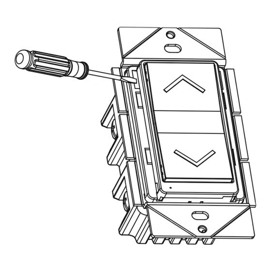
To Replace the Face Cover,
use a small screwdriver to
pry off the cover
0207160034-07
Advertisement
Table of Contents

Subscribe to Our Youtube Channel
Related Manuals for Enerwave ZW500DM-PLUS


Summary of Contents for Enerwave ZW500DM-PLUS
- Page 1 Z-Wave devices can be automatically powered on by programmed events. Unattended or unintentional operation could result in hazardous conditions. Z-Wave enabled devices should never be used to supply power to, control, or monitor medical and/or life support equipment. To enable the 3-way function install the ZW3K-N in conjunction with the ZW500DM-PLUS. For use with incandescent, halogen, LED, and CFL lights. Use copper wires only. © 2017 Enerwave Home Automation ● WWW.ENERWAVEAUTOMATION.COM ● CA, USA...
- Page 2 Step 3. Follow the On-Screen instructions in the Control Panel on adding or removing rooms, scenes, other devices, and other functions and features. Step 4. To reset the ZW500DM-Plus manually, simply press the "ON" or "OFF" paddle on the switch 3 times and hold for 3 seconds on LED/CFL Derating Chart the 3rd press.
Need help?
Do you have a question about the ZW500DM-PLUS and is the answer not in the manual?
Questions and answers