
Subscribe to Our Youtube Channel
Related Manuals for Birlea MERLIN HIGH SLEEPER


Summary of Contents for Birlea MERLIN HIGH SLEEPER
-
Page 2: Health And Safety
ASSEMBLY INSTRUCTIONS MERLIN HIGH SLEEPER IMPORTANT: READ THESE INSTRUCTIONS CAREFULLY BEFORE ASSEMBLING OR USING YOUR MERLIN HIGH SLEEPER FRAME. PLEASE KEEP THESE INSTRUCTIONS FOR FUTURE REFERENCE. HEALTH & SAFETY: DO NOT jump on this bed frame. DO NOT use this bed frame if any parts are missing, damage or worn. - Page 3 13 x 3 12 x 3 Page 2 of 25...
-
Page 4: Parts List
PARTS LIST HARDWARE LIST: Carton 2 of 3 Carton 1 of 4: Part Description Part Description CAM NUT 15mm Back Side Panel CAM BOLT Back Base Panel WOOD DOWEL M8 x 30mm Front Base Panel JCBC SCREW M6 x 50mm Base Bottom Support Panel M6 STEEL NUT M6 x 40mm UNITAR SCREW... - Page 5 Insert hardware part A & part B using a screwdriver (not provided). Insert hardware part C using a small mallet (not provided). Insert hardware part K using a small mallet (not provided). Attach hardware part T with screw J using screwdriver (not provided). Insert hardware Q using a small mallet (not provided).
- Page 6 Insert hardware part A & part B using a screwdriver (not provided). Insert hardware part C using a small mallet (not provided). Insert hardware part K using a small mallet (not provided). Attach hardware N with screw I using screwdriver (not provided).
- Page 7 Attach the right panel (10) and table left panel (21) to the bottom support panel (22) with screw (F) by using allen key (V) and tighten clockwise. DO NOT use any power tools as this may damage the frame and will invalidate any claim. Attach the ladder bottom support panel (12) and ladder step panel (13) to the right panel (10) with screw (F) by using allen key (V) and tighten clockwise.
- Page 8 Attach the ladder back panel (11) to right panel. DO NOT use any power tools as this may damage the frame and will invalidate any claim. with PVC Nail Attach the left panel (9) to the ladder back panel (11) with screw (F) by using allen key (V) and tighten clockwise.
- Page 9 Attach cabinet back support panel (16) to left panel (9) with screw (F) by using allen key (V) and tighten clockwise. Attach cabinet plinth panel (15) and (33) to left panel (9). DO NOT use any power tools as this may damage the frame and will invalidate any claim. Attach cabinet bottom panel (14) to left panel (9) with screw (F) by using allen key (V) and tighten clockwise.
- Page 10 Attach left side panel (1) to bottom panel (14) and back support panel (16) with screw (F) by using allen key (V) and tighten clockwise. DO NOT use any power tools as this may damage the frame and will invalidate any claim. Attach table bottom panel (23) to table left panel (21) with screw (F) by using allen key (V) and tighten clockwise.
- Page 11 Fix the table top (19) to the table left panel (21) by using a screwdriver (not providedDO NOT use any power tools as this may damage the frame and will invalidate any claim. Unlock Lock Attach table back panel (20) to table left panel (21) with screw (F) by using allen key (V) and tighten clockwise.
- Page 12 Fix table back panel (20) to table top panel (19) with screw (F) by using allen key (V) and tighten clockwise. DO NOT use any power tools as this may damage the frame and will invalidate any claim. Attach back bottom panel (8) to left side panel (1) with screw (D) & hardware (E) by using allen key (V) and tighten clockwise.
- Page 13 Attach right side panel (2) with screw (D) & screw (F) by using allen key (V) and tighten clockwise. DO NOT use any power tools as this may damage the frame and will invalidate any claim. Page 12 of 25...
- Page 14 Attach cabinet back panel (32) with screw (J) using a screwdriver (not provided) and nail (L) by using small mallet (not provided). DO NOT use any power tools as this may damage the frame and will invalidate any claim. Page 13 of 25...
- Page 15 Fix back base panel (4) with screw (F) by using allen key (V) and tighten clockwise. DO NOT use any power tools as this may damage the frame and will invalidate any claim. Page 14 of 25...
- Page 16 Fix back side panel (3) with screw (D) & hardware (E) by using allen key (V) and tighten clockwise. DO NOT use any power tools as this may damage the frame and will invalidate any claim. Page 15 of 25...
- Page 17 Attach front base panel (5) with screw (F) by using allen key (V) and tighten clockwise. DO NOT use any power tools as this may damage the frame and will invalidate any claim. Page 16 of 25...
- Page 18 Attach left and right front side panels (6) & (7) with screw (D) and hardware (E) by using allen key (V) and tighten clockwise. Fix hardware (R) with screw (I) by using screwdriver (not provided). DO NOT use any power tools as this may damage the frame and will invalidate any claim. Page 17 of 25...
- Page 19 Fix left and right front side panels (6) & (7) with screw (F) by using allen key (V) and tighten clockwise. Insert hanger pipe (O) and hardware (M) as shown. DO NOT use any power tools as this may damage the frame and will invalidate any claim. Page 18 of 25...
- Page 20 Fix door panel (18) to left side panel (1) with hinges (S) and screw (I) using a screwdriver (not provided). Insert movable panel (24) as shown. DO NOT use any power tools as this may damage the frame and will invalidate any claim. Door Door Door...
- Page 21 Fix drawer left & right panels (28) & (29) to drawer back panel (27) with screw (G) by screwdriver (not provided). DO NOT use any power tools as this may damage the frame and will invalidate any claim. Insert drawer bottom panel (30) as shown. Page 20 of 25...
- Page 22 Fix drawer front panel (26) by screwdriver (not provided). DO NOT use any power tools as this may damage the frame and will invalidate any claim. Unlock Lock Fix hardware (U) onto the drawer left panel & drawer right panel (28) & (29) using screw (J) by screwdriver (not provided).
- Page 23 Fix hardware (X) as shown. Insert drawer as shown. DO NOT use any power tools as this may damage the frame and will invalidate any claim. Page 22 of 25...
- Page 24 Cover screw hole with sticker (W) as shown. Page 23 of 25...
- Page 25 Cover screw hole with sticker (W) as shown. Page 24 of 25...
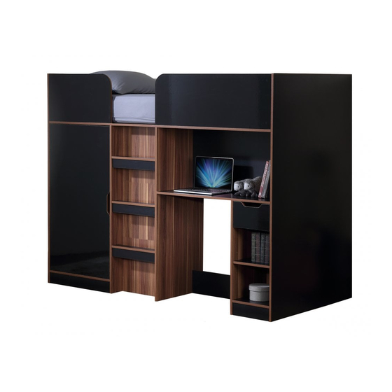
- Page 26 Your MERLIN HIGH SLEEPER is now completely assembled. Periodically check to ensure that the components are in their proper postition, free from damage. Also, make sure the connectors are tight and secure. Page 25 of 25...
Need help?
Do you have a question about the MERLIN HIGH SLEEPER and is the answer not in the manual?
Questions and answers