
Related Manuals for SteelMax SBM-500

Summary of Contents for SteelMax SBM-500
- Page 1 The tools of innovation. OPERATOR’S MANUAL SBM-500 STATIONARY BEVELING MACHINE 112 Inverness Circle East Suite F Englewood, CO 80112 1– 87STEELMAX, FAX 303 – 690 – 9172 www.steelmax.com sales@steelmax.com...
-
Page 2: Table Of Contents
Contents 1. GENERAL INFORMATION ....................3 1.1. Application ......................... 3 1.2. Technical data......................3 1.3. Equipment included ....................4 1.4. Dimensions ........................ 5 1.5. Design ........................6 2. SAFETY PRECAUTIONS ....................7 3. STARTUP AND OPERATION ................... 9 3.1. Preparing ........................9 3.2. -
Page 3: General Information
1. GENERAL INFORMATION 1.1. Application The SBM-500 is a stationary machine designed to bevel plates made of carbon steel, stainless steel, or aluminum alloys. The workpieces can be machined at an angle of 15–60° and to the bevel width of up to 30 mm (1-3/16″). -
Page 4: Equipment Included
6 6 mm hex wrench 1 unit 7 3.5 mm hex wrench 1 unit 8 14 mm combination wrench 1 unit 9 T15 torx screwdriver 1 unit 10 Grease for screws 1 unit – Operator’s manual 1 unit SBM-500 Operator’s Manual... -
Page 5: Dimensions
SBM-500 1.4. Dimensions 1276 mm (50″) SBM-500 Operator’s Manual... -
Page 6: Design
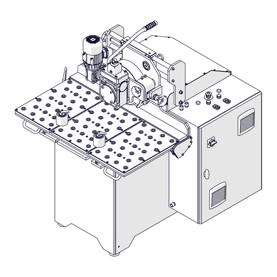
SBM-500 1.5. Design Control cabinet Milling unit Feed unit Table Collision prevention Bevel angle adjustment unit Milling head penetration adjustment unit Chip container SBM-500 Operator’s Manual... -
Page 7: Safety Precautions
18. If the cutting edge of an insert is worn, rotate all inserts by 90°. If all edges are worn, install new inserts specified in this Operator’s Manual. 19. Do not make bevels or use workpieces whose parameters differ from those specified in the technical data. SBM-500 Operator’s Manual... - Page 8 28. Do not leave the machine when it operates. 29. If you are not going to use the machine for an extended period, put anti-corrosion material on the steel parts. SBM-500 Operator’s Manual...
-
Page 9: Startup And Operation
Use the 6 mm hex wrench to tighten the handle (1, Fig. 2). Then, use the 8 mm hex wrench to detach the machine from the brackets (2). Fig. 2. Installing the handle and detaching the machine from the base SBM-500 Operator’s Manual... - Page 10 SBM-500 Use a pallet jack to lift the machine from left or right (Fig. 3), and then transport it to the worksite. Fig. 3. Transporting the machine to the worksite SBM-500 Operator’s Manual...
- Page 11 Rotate the feet that are not in contact with the surface so that they rest on it (1, Fig. 4). Then, use the 18 mm flat wrench to tighten the nuts, which will lock the feet in this position. Fig. 4. Levelling the machine on the surface SBM-500 Operator’s Manual...
-
Page 12: Setting The Table And The Feed Unit
(2) to lock the table in this position. Next, use the handle (3) to rotate the feed unit so that the screw makes contact with the bumper (4). Fig. 5. Moving the table and lowering the feed unit SBM-500 Operator’s Manual... -
Page 13: Setting The Bevel Angle And Milling Head Penetration
(4) so that the vertical base comes in contact with the horizontal base (Fig. 6b). Lock the lever in this position. CORRECT INCORRECT ✓ Fig. 6. Setting the milling head penetration to zero: incorrect (a), correct (b) SBM-500 Operator’s Manual... - Page 14 Before the first pass, move the vertical base (1) away from horizontal base (2, Fig. 8). To do this, unlock the lever (3), and then use the knob (4) to move the vertical base to a gap (X) that is correct for a single pass. SBM-500 Operator’s Manual...
- Page 15 10.1 30.2 23.6 19.0 15.7 13.1 27.5 21.5 17.3 14.3 11.9 33.6 24.7 19.3 15.6 12.9 10.7 29.9 22.0 17.2 13.9 11.4 26.1 19.2 15.0 12.1 10.0 22.4 16.5 12.9 10.4 18.7 13.7 10.7 14.9 11.0 11.2 SBM-500 Operator’s Manual...
- Page 16 ‘d’ of 4 mm. Angle 15° 20° 25° 30° 35° 40° 45° 50° 55° 60° Maximum allowed gap-increase per a single pass [mm] Fig. 8. Setting the milling head penetration before the first pass SBM-500 Operator’s Manual...
-
Page 17: Setting The Feed Wheel Height
Use the knob (1, Fig. 9) to set the feed wheel at such a height so that the workpiece is firmly pressed to the horizontal base (2) during rotation of the feed wheel. Then, use the nut (3) to lock the knob in this position. Fig. 9. Setting the feed wheel height SBM-500 Operator’s Manual... -
Page 18: Tilting The Feed Unit
(1, 2, Fig. 10) to tilt the feed unit. Do this when milling narrow workpieces or after moving the vertical base away from the horizontal base. Fig. 10. Tilting the feed unit Then, adjust the feed wheel. SBM-500 Operator’s Manual... -
Page 19: Adjusting The Feed Wheel
Next, lock the knob (1) and lever (2) in this position. Do not let the feed wheel or its cover come in contact with the milling head or vertical base. Use the knob 3 Use the knob 4 Fig. 11. Adjusting the feed wheel SBM-500 Operator’s Manual... -
Page 20: Operating
Between the vertical base and the horizontal base, put the bevel height gauge related to the angle. On the gauge scale, read the bevel height related to the gap. Make sure that the vertical base is not in contact with the milling head. SBM-500 Operator’s Manual... - Page 21 Before you set the angle, set the penetration of the milling head to zero. If needed, tilt the feed unit and adjust the feed wheel. Clean the machine with a cotton cloth and no chemical agents. SBM-500 Operator’s Manual...
-
Page 22: Removing And Installing The Milling Head
(4). To install, put the milling head on the spindle and prevent the rotation of the spindle. Then, use the removed screw and washer to tighten the milling head. Fig. 13. Removing the milling head SBM-500 Operator’s Manual... -
Page 23: Replacing The Cutting Inserts
(3). Rotate the cutting insert by 90° and reinstall it or replace with a new insert if all four edges are worn. Press the cutting insert so that its bottom is in full contact with the shim, and then tighten with the fixing screw. Fig. 14. Replacing the cutting inserts SBM-500 Operator’s Manual... -
Page 24: Accessories
To install the attachment, set the milling head penetration to zero (Fig. 6b). Then, move the roller from the left groove to the right groove (1, Fig. 15). Next, lift the feed unit (2) and move the attachment into the left groove (3). Fig. 15. Installing the pipe attachment SBM-500 Operator’s Manual... - Page 25 2° (Fig. 10). Next, set the height feed wheel height and adjust the wheel (Fig. 9, 11) so that the pipe is pressed to the attachment and horizontal base when the feed wheel rotates (6, Fig. 16). SBM-500 Operator’s Manual...
-
Page 26: Cutting Tools
After the machine starts, the feed wheel moves the pipe to the milling head. 4.2. Cutting tools Part number Part name PLY-000396 Cutting insert for steel (10 required, sold 10 per box) PLY-000408 Cutting insert for aluminum (10 required, sold 10 per box) SBM-500 Operator’s Manual... -
Page 27: Table
Allows the machine to bevel longer plates. Part number: STL-0573-37-00-00-0 To assemble the table, put it upside down (Fig. 18). Use the 16 mm and 17 mm flat wrenches to attach the legs (1) and bracket (2). Fig. 18. Assembling the table SBM-500 Operator’s Manual... - Page 28 Next, use the 18 mm flat wrench to tighten the nuts (2) to lock the feet in this position. Then, align the faces of the tables (3). Be careful not to catch your hands between the handle and table (4). Fig. 19. Using the table SBM-500 Operator’s Manual...
-
Page 29: Attachment For Narrow Plates
Plate width Minimum allowed plate thickness 30–50 mm (1.18–1.97″) 10 mm (0.39″) ≥ 50 mm (1.97″) 3 mm (0.12″) To install the attachment, remove the rollers (1, Fig. 20) and move the attachment into the table grooves. SBM-500 Operator’s Manual... - Page 30 Set the required bevel angle and milling head penetration (Fig. 6, 7, 8). Move the plate (3, Fig. 21) to the vertical base (4). Move the attachment to the plate (5) and lock the levers (6). Fig. 21. Positioning the attachment SBM-500 Operator’s Manual...
-
Page 31: Exploded Views And Parts List
ITEM PART NUMBER DESCRIPTION Q-TY SMR-000005 GREASE FOR SCREWS 5g KLC-000061 14 MM COMBINATION WRENCH KLC-000066 T15 WRENCH WITH HANDLE KLC-000065 3.5 MM HEX WRENCH KLC-000011 8 MM HEX WRENCH PJM-000010 TOOL CONTAINER ZST-0573-42-00-00-0 BEVEL HEIGHT GAUGES SET SBM-500 Operator’s Manual... - Page 32 SBM-500 SBM-500 Operator’s Manual...
- Page 33 HEX SOCKET HEAD CAP SCREW M5x16 SNA-000041 GUIDE SRB-0573-29-00-00-0 LOCKING BOLT ASSY SRB-000047 HEX SOCKET HEAD CAP SCREW M10x30 PDK-000026 ROUND WASHER 10.5 WSP-0573-28-00-00-0 CLAMPING BLOCK SUPPORT LPA-0573-27-00-00-0 CLAMPING BLOCK NKR-000019 HEX NUT M8 KRP-0573-01-00-00-0 FRAME OSL-0573-10-00-00-0 SIDE TABLE COVER SBM-500 Operator’s Manual...
- Page 34 HEX SOCKET HEAD CAP SCREW M8x35 PRW-000068 CARRIAGE STP-000002 BRACKET D75 ZLC-000160 CABLE GLAND NKR-000084 LOW HEX NUT M16x1.5 ZLC-000153 CABLE GLAND SZF-0573-05-00-01-0 CONTROL BOX ASSY ZBN-0573-06-00-00-0 CHIP CONTAINER ASSY KBL-0573-31-00-00-0 SPINDLE MOTOR WIRE SET *not shown in the drawing SBM-500 Operator’s Manual...
- Page 35 GEARBOX COVER RING PRS-000019 EXTERNAL RETAINING RING 28z WPS-000045 KEY 8x7x40 WLK-0573-04-16-00-0 SHAFT WPS-000077 KEY 8x7x30 RDK-000016 GEARBOX NKR-000002 NUT M10 SRB-000114 HEX SOCKET HEAD CAP SCREW M6x20 PLY-0573-04-08-00-0 GEARBOX PLATE ASSY SRB-000141 HEX SOCKET HEAD CAP SCREW M8x14 SBM-500 Operator’s Manual...
- Page 36 LEVER ASSY PDK-000022 ROUND WASHER 8.4 PDK-000051 SPRING WASHER 8.2 SRB-000156 HEX SOCKET HEAD CAP SCREW M8x35 PKR-000124 COVER PCV 40 SRB-000102 HEX SOCKET HEAD CAP SCREW M6x12 KBL-0573-04-34-00-0 FEED MOTOR CABLE * not shown in the drawing SBM-500 Operator’s Manual...
- Page 37 HEX SOCKET HEAD CAP SCREW M6x10 ZGR-0573-02-10-00-0 CHIPS DRIFT FENDER II ZGR-0573-02-09-00-0 CHIPS DRIFT FENDER I ZGR-0573-02-08-00-0 TOP CHIPS DRIFT FENDER SRB-000156 HEX SOCKET HEAD CAP SCREW M8x35 PLY-0573-02-04-00-0 MOUNTING PLATE ASSY PLY-0573-02-03-00-0 MOVING PLATE NKR-000003 HEX NUT M12 WSP-0573-02-05-00-1 MOTOR SUPPORT SBM-500 Operator’s Manual...
- Page 38 MILLING CUTTER PLY-000396 MILLING CUTTER INSERT SRB-000083 HEX SOCKET HEAD CAP SCREW M5x16 WPS-0573-02-02-00-0 TRC-0573-02-01-00-0 MOTOR PLATE SLN-000200 MOTOR 400V PRZ-0573-02-06-00-0 NIPPLE ZLC-000160 CABLE GLAND PLY-000439 SHIM SRB-000417 CLAMP SCREW SRB-000418 SHIM SCREW PDK-000164 ROUND WASHER 12x18x1 SBM-500 Operator’s Manual...
- Page 39 BZA-0573-03-04-00-0 VERTICAL BASE PLATE UCW-0573-03-03-00-0 HANDLE SRB-000148 HEX SOCKET HEAD CAP SCREW M8x20 STL-0573-03-01-00-1 TABLE PRT-0573-03-13-00-0 LOCKING ROD ASSY PRW-000068 CARRIAGE WSP-0573-03-09-00-0 GUIDE SUPPORT KLK-000083 DOWEL PIN 6n6x18 SNA-000040 GUIDE SRB-000083 HEX SOCKET HEAD CAP SCREW M5x16 SBM-500 Operator’s Manual...
- Page 40 EMERGENCY BUTTON STK-000010 CONNECTOR PRC-000042 GREEN BUTTON PRC-000043 RED BUTTON PTN-000038 POTENTIOMETER PRC-000044 START-STOP BUTTON PRP-000014 STRAIN RELIEF NKR-000198 STRAIN RELIEF NUT M20x1.5 SZF-0573-05-01-00-0 CONTROL BOX RZL-000017 3-GEAR DISCONNECTOR 40A FLT-000011 AIR FILTER NKR-000165 STRAIN RELIEF NUT M25x1.5 SBM-500 Operator’s Manual...
- Page 41 CIRCUIT BREAKER C25 BZP-000031 CIRCUIT BREAKER C6 BZP-000027 CIRCUIT BREAKER C6 3PS1 ZSL-000027 POWER SUPPLY BZP-000019 CIRCUIT BREAKER B1 BZP-000019 CIRCUIT BREAKER B1 BZP-000019 CIRCUIT BREAKER B1 PZK-000044 EMERGENCY STOP MODULE PDS-000024 SOCKET PZK-000030 RELAY 24VDC PDS-000024 SOCKET SBM-500 Operator’s Manual...
- Page 42 SBM-500 ITEM PART NUMBER DESCRIPTION Q-TY PZK-000030 RELAY 24VDC PDS-000024 SOCKET PZK-000030 RELAY 24VDC PRZ-0573-99-01-00-0 SPINDLE FREQUENCY INVERTER 3x480V MDL-000083 DYNAMIC BRAKING MODULE PRZ-0573-99-03-00-0 FEED FREQUENCY INVERTER 3x480V SBM-500 Operator’s Manual...
-
Page 43: Declaration Of Conformity
6. DECLARATION OF CONFORMITY Declaration of Conformity PROMOTECH sp. z o.o. ul. Elewatorska 23/1 15-620 Białystok Poland We declare with full responsibility that: SBM-500 Stationary Beveling Machine is manufactured in accordance with the following standards: • EN 60204-1 • EN ISO 12100 •... -
Page 44: Warranty Card
WARRANTY CARD No..................in the name of Manufacturer warrants the SBM-500 Stationary Beveling Machine to be free of defects in material and workmanship under normal use for a period of 12 months from the date of sale. This warranty does not cover cutting inserts as well as damage or wear that arise from misuse, accident, tempering, or any other causes not related to defects in workmanship or material.
Need help?
Do you have a question about the SBM-500 and is the answer not in the manual?
Questions and answers